3-7
Service Manual
M
AINTENANCE
Integrated
Rectifier
SR1
Main
Transformer
T1
CR7
18 and 24
VAC
36 VAC
Center-
Tapped
Power
Control Board
PC1
Contactor Control Signal
Command Signal
Torch Cap Safety Circuit
Torch Trigger Circuit
Work (+)
Secondary
Primary
Fan
Motor
FM
3
2
4
5
10
1234
1234
1234
1234
12345678901234
12345678901234
12345678901234
Pilot (+)
Electrode (-)
AC or DC Control Circuits
1
Φ
Power
Cutting and Pilot Current Circuits
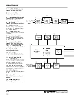
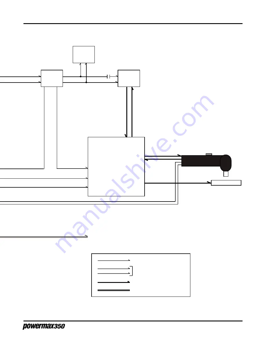
Figure 3-2.2 Functional Block Diagram, 200 Volt
To Torch
Air Supply
115
VAC
DC Power
7-98


