Page 22
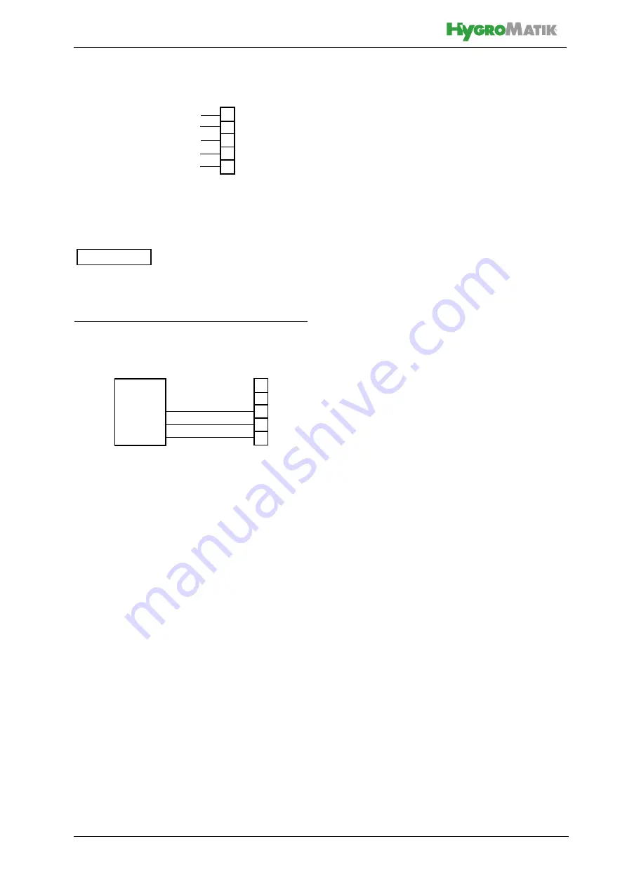
Active r.h. sensors need an external supply
voltage. For that purpose, terminal 3 has a
+20 VDC offering.
8.5 Connection diagram
Pls. find the full wiring diagram in the „Unit
control“ chapter, section „Main PCB connec-
tions“ of the co-applicable „Control Standard“
manual.
8.6 Electrical installation check
list
Check electrical installation with respect to
customer-site requirements and local power
supply regulations.
Safety interlock properly wired
across terminals 1 and 2?
Supply voltage in accordance with
name plate voltage rating?
All ectrical connections made accor-
ding to the wiring diagram?
R.h. sensor properly connected with
respect to signal type (0...10 V,
0...20 mA, 0...140
Ω
) and supply
voltage (only when r.h. sensor is in
use)?
All screw terminal connections prop-
erly tightened?
Have all electrical cable and plug
connections been properly tighte-
ned?
Proper unit gounding made?
3
4
5
6
7
20 VDC
GND
0...10V
0...20mA
Terminals for
control signals
0...140 Ohm
3OHDVHQRWH
3
45
6
7
+20 VDC
Humidity sensor
Terminal strip
GND
0...10V
Exemplary 0...10V humidity
sensor connection


