


Page 90
Glossary ctd. (1)
Floating max. limiter
35
The floating max. limiter is an additional function when the control is operated with the internal PI controller. It
serves for protection against excessive humidification of the channel. In case of the room sensor sending a
demand while the channel has already reached its maximum humidity capacity, a floating max. limiter
allows for a much more sensitive limitation of the humidification when compared to a max. hygrostat. While
the max- hygrostat switches off only when the maximum humidity is reached, the floating max. limiter tracks
the humidity progress and turns down the humidification based on a settable control curve until a defined
max. humidity is reached. This aimes to ensure that no excessive humidification may occur in the channel.
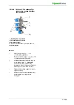
To use this function, a 2nd humidity sensor must be mounted in the channel (typical mouting position is the
range where the steam is introduced into the channel by the humidifier).
Connecting the 2nd humidity sensor
The 1st humidity sensor must be of the "Humidity sensor with 0...10 V output voltage" type to allow for the
implementation of the floating max. limiter function. The second humidity sensor is than wired to the current
input of the mainboard. To allow for this, the sensor must feature a 4...20 mA current output signal.
Activating the floating max. limiter
Activating is accomplished by setting the "Control settings" parameter in submenue "Control" to "11". If no
2nd humidity sensor is connected, the parameter setting is not saved.
Parameter settings for the floating max. limiter
For the floating turning-down of the humidity set value, the control curve steepness may be set with the "PI-
controller_max_gain" parameter. Factory pre-setting (FP) is "5". The humidity set value for the shut-down
point is defined by the "Humidity_set_max" parameter (FP = 80%).
Service_operating_hours
37
The number of hours after which a service is recommended is stored in the control in the "Service-
interval_operating_hours" parameter. Once the default value has been reached, the message
"Service_operating hours" is displayed. "Operating_hours_until_message" is used to show the number of
hours until the service message is displayed. Once the service has been performed, the service operating
hours counter has to be reset with "Operating_hours_reset". This also deletes the service message.
Internal actuator signal
42
Actuator signal for the control of the power element of the unit concerned.
Max. humidification output
43
Reduction of output power to 25... 100% of the nominal output. Can lead to improved control behaviour at
lower output requirements.
1-step-operation
44
On/off operation of the High Pressure System without control function through a potential free contact
suitable for low voltage, to be supplied on-site. The control can, for example, be implemented using a
Hygrostat [6]
, which has to be connected to a potential free make contact between terminals 3 and 5 of
the control.
Humidification
47
The unit humidifies, if a
Hygrostat [6]
, an
External control [73]
, a Humidity sensor or a
Software
control command [12]
has issued a
Demand [5]
and the
Interlock (safety) system [11]
is closed.
Correction_x_signal
49
Used for the calibration of a humidity sensor output signal as the
Input signal [72]
of the control (x = "V",
"mA", "
Ω
").
Exhaust air cooling
62
Operational mode that is either an made-to-order option or, in case of a
c
ombined system [114]
, may be
selected by setting the "10:Functions/12" parameter (
Digital_input-function [98]
). For activating the
exhaust air cooling, the
Digital input [97]
must be lifted to the
Auxiliary voltage [105]
potential. The
system then operates in
1-step-operation [44]
mode with 100% power output for exhaust air cooling.
Practically speaking, instead of using a manually operated switch, it is very common to accomplish the
switching by means of a relay-operated NO contact that is controlled by the Business Control System.
Load level
64
The HPS/LPS system distinguishes between different load levels, depending on the number of nozzle
sections being controlled. The load levels are differentiated from each other by
switchover points [81
]
voneinander getrennt.
Relay assignment
65
If the basic relay or additional relays which may be present are not used for signalling but for direct load
switching, the maximum contact load 250 VAC/8 A must be taken into account
Output signal
69
Signal 0... 10 V on pins 12 and 13 (GND) of ST07 on the mainboard, which is proportional to the input signal.
Can be used to control downstream units.
Input signal
72
The electrical signal fed to the control at the ST08 plug of the mainboard. Depending on the signal
characteristic (Voltage, current or resistivity progress), a certain pin of the corresponding plug is used. The
signal range of the input signal (e.g. 0...10V) is to be adapted by setting of the related parameter. Using the
Correction_x_signal [49] parameters, the output signal of a humidity sensor may be calibrated.
External controller
73
The control uses the output signal of an external controller to control the power element for steam
generation. The input level of the control can be adapted to different signal types and value ranges. Other
possible input signals are the output signal of a humidity sensor (in connection with the internal PI controller),
the switching contact of a
Hygrostat [6]
(for
1 step operation [44]
) and a
Software command [12]
via
the
Communication interface [13]
.
Dropout delay
74
By assigning the "8" value to one of the relay contacts, a delayed control signal is made available for. The
dropout delay is set with the "Humidification_off_delay" paramter. Factory default is 60 s.
Main contactor
75
The installed main contactor is labelled K1. The operating cycles of the main contactor is monitored and
compared with the value specified by the manufacturer for the expected service life. When the stored value
is reached, the message "Service_main_contactor_K1" is generated. After the main contactor has been
replaced, the status message must be deleted, using the
Main_contactor_K1_Reset = "1" parameter.