background image

ST16135-00E

19

7

Operating Instructions

7.2

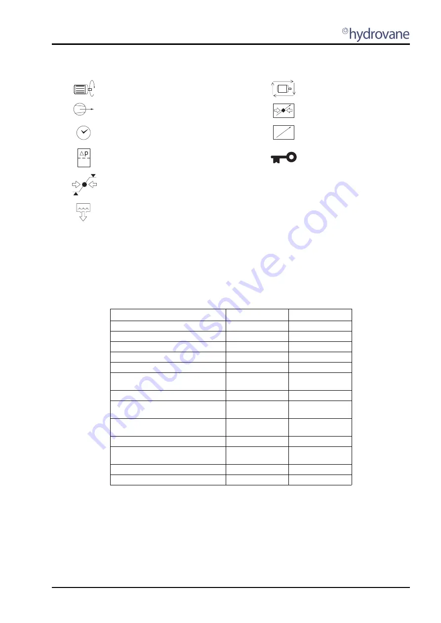
Operational Display Symbols

7.3

LED Indicators (Fig 7.2)

STATUS:

Green

°

FAULT

Red

l

The indicator states are shown in Table 7.1.

Table 7.1 - Compressor Status and LED Indicators

Key:

ON

Illuminated continuously

FF

Fast flash: on/off four times per second

SF

Slow flash: on/off once per second

IF

Intermittent flash: on/off every four seconds

OFF

Extinguished continuously

*

SF for alarm condition

Motor running

Power failure auto-restart (optional 
function)

Loaded

Remote load or remote pressure 
regulation active

Amount of time, timer

Remote start/stop

Filter, differential pressure

Normal operational mode:

Selected item locked as
temporary default display

Menu mode:

Page item locked 
(adjustment inhibited)

Pressure set point indication 
(upper & lower set point indicators 
displayed independently)

Condensate drain active (optional 
function)

Compressor State

LED Status  °

LED Fault  

l

Shutdown Error

OFF

FF

Startup Init

OFF

OFF *

Start Inhibit Check

OFF

OFF *

Start Inhibit Condition

OFF

SF

Ready to Start

OFF

OFF *

Blowdown                           (If Load Request)
                                                       (Otherwise)

FF

IF

OFF *
OFF *

Standby

IF

OFF *

Start motor in Star/Delta   (If Load Request)
                                                       (Otherwise)

FF

IF

OFF *
OFF *

Load Delay                         (If Load Request)

(Otherwise)

FF

IF

OFF *
OFF *

Load

ON

OFF *

Reload Delay                     (If Load Request)

(Otherwise)

FF

IF

OFF *
OFF *

Standby Run-on-Time

IF

OFF *

Stop Run-on-Time

SF

OFF *

Summary of Contents for HB18

Page 1: ...User Handbook HV04 HV45 Models ACE Stationary Air Compressors ST 16135 00 Iss E 05 2009 GB...

Page 2: ......

Page 3: ...ion 9 4 2 Lifting and Handling Fig 4 1 and Fig 4 2 9 4 3 Model Weights 9 5 Installation and Commissioning 11 5 1 Positioning Your Compressor Basic Requirements 11 5 2 Ventilation Fig 5 1 11 5 3 Electr...

Page 4: ...Oil Filter Replacement Fig 9 3 24 9 10 Oil filling Top up Fig 9 3 25 9 11 Air Filter Replacement Fig 9 2 25 9 12 Oil Separator Replacement Fig 9 2 25 9 13 Clean Oil Cooler Aftercooler Fig 9 4 25 9 14...

Page 5: ...ir com 1 5 Model Range This Handbook relates to all ACE HV04 HV45 vertical range compressors and hypac models V04ACE07 4035D400 50Hz model V04ACE10 4035D400 50Hz model V04ACE07 4035S400 50Hz model V04...

Page 6: ...el V45ACE08 2036D150 60Hzmodel V45ACE10 2036D150 60Hzmodel V45ACE08 5736D150 60Hzmodel V45ACE10 5736D150 60Hz model The last three digits of the product code represent mark number changes you may rece...

Page 7: ...he compressor s vent down cycle is complete Release any pressure contained in the aftercooler or associated pipework Check that the compressor pressure gauge reads zero Do not proceed until it does Ca...

Page 8: ...e is any suspicion of aspiration into the lungs for example during vomiting admit to hospital immediately Pressure injection Obtain immediate medical attention even if injury appears minor Spillage So...

Page 9: ...e required Conditions or applications which prevent the compressor temperature stabilising between these parameters should be avoided Single speed HV30 HV45 and all RS units have automatic stop start...

Page 10: ...or 10 5 7 5 Servo Valve bar 8 0 or 11 0 8 0 Run on Time after PU secs RT 120 60 Run on Time to Stop secs ST 2 Pressure Display Units P 0 bar 1 psi 2 kpa Temperature Display Units T 0 C 1 F Vacuum Rel...

Page 11: ...8 0 Unload Pressure bar PU 8 5 or 10 5 8 5 Servo Valve bar 9 0 or 11 0 9 0 Run on Time after PU secs RT 60 8 bar 90 10bar 60 Run on Time to Stop secs ST 2 Pressure Display Units P 0 bar 1 psi 2 kpa Te...

Page 12: ...8 5 Servo Valve bar 9 0 or 11 0 9 0 Run on Time after PU secs RT 60 8 bar 90 10bar 60 Run on Time to Stop secs ST 2 Pressure Display Units P 0 bar 1 psi 2 kpa Temperature Display Units T 0 C 1 F Vacuu...

Page 13: ...the hypac or compressor and place it in the desired location Fig 4 2 ACED HV11 22 Hypac Compressor Damage to mountings may occur if you attempt to slide the compressor into position Take care when mo...

Page 14: ......

Page 15: ...ated in a moderate ambient temperature If temperatures frequently fall below 0 C consult your Hydrovane D istributor A different grade of oil may be required Compressor air intake and exhaust grills h...

Page 16: ...that the compressor is filled with approved oil and that all plugs are fitted securely Refer to Section 9 6 Access Panel Removal to remove the top panel so that the compressor pressure gauge can be v...

Page 17: ...vane standard single speed compressors feeding a common pressure system the minimum air line pressure of the RS compressor must be limited to the lowest maximum air line pressure of the single speed m...

Page 18: ......

Page 19: ...st savings due to the offload power reduction During offload run on time at minimum pressure the compressor will either stop with no air demand or return to onload running if more air is required Auto...

Page 20: ...the oil system is filtered by an oil filter L An oil level sight glass M is mounted adjacent to the oil filter The compressor is filled and topped up with oil via the oil filler N The sight glass M w...

Page 21: ...n and red LED indicators for three seconds Fig 7 1 The display then shows the software version code for a further three seconds before showing the normal operating display Single speed compressors all...

Page 22: ...s Mode Press the green START button the compressor will start and run continuously within the load unload PL PU pressure set points to match system demand On initial start with no pressure in the syst...

Page 23: ...r Remote start stop Filter differential pressure Normal operational mode Selected item locked as temporary default display Menu mode Page item locked adjustment inhibited Pressure set point indication...

Page 24: ......

Page 25: ...mperature Display Units h 01 15 Error Log A selected item will flash press plus up or minus down button to change a value or select an alternative press ENTER to select During changes if no key activi...

Page 26: ...adjustment or a lower pressure is required then carry out the following procedure a Turn the electrical supply on at the isolator disconnect the air outlet valve from the system and fit an air silence...

Page 27: ...Distributor 9 3 Servicing RS Servicing intervals and procedures are the same as specified for the standard fixed speed compressor of the same power kW rating The speed control unit does not require an...

Page 28: ...the top panel from the snap fit location pegs or location slots and lift clear of the compressor Check that the compressor pressure gauge reads zero 9 7 Oil Draining and Filter Replacement Fig 9 2 and...

Page 29: ...g area behind the cabinet filter B All discarded items and waste oil must be disposed of in an approved manner 9 14 Cabinet Air Filter Remove the disposable filter located in the rear panel by sliding...

Page 30: ...extreme ambients HPO oil should be used at the 2000 hour oil change periods If the oil is working above these temperatures the oil life will be significantly reduced If changing to Fluid Force Clear...

Page 31: ...X X X Check motor for damage X X X X Check motor starter for loose connections X X X X Check motor cables and earth X X X X Check motor for vibration X X X X Check flexible oil pipes X Check oil seal...

Page 32: ...otor for damage X X X Check motor starter for loose connections X X X Check motor cables and earth X X X Check motor for vibration X X X Check flexible oil pipes X Check oil seal for leakage X Check d...

Page 33: ...low General fault Emergency stop Excess pressure Power failure Above set temperature limit Lubrication oil oil level Dewpoint Motor Service due maintenance Filter differential filter service Er 0010 E...

Page 34: ...enu P21 For authorised engineers to install or service compressors as part of an approved installation or maintenance program 10 10 Diagnostic Menu P22 Allows an authorised technician to check and tes...

Page 35: ......

Page 36: ...ion of the Technical Publications Department Gardner Denver Ltd Gardner Denver Ltd Claybrook Drive Washford Industrial Estate Redditch Worcestershire B98 ODS United Kingdom Tel 44 0 1527 525522 Fax 44...

Reviews: