background image


- 3 - 


SADDLE TAPPING VALVE INSTALLATION ON THICK WALL PIPE 


NOTE:


State and local plumbing codes may prohibit use of saddle tapping valves.  An Inlet Adapter Valve 
Assembly (P/N 42500004) is available as an alternate installation (See Page 4).


1.  Locate and shut off source water supply line (See 

Page 2, Steps 1 & 2 with associated Notes).   


CAUTION:

  DO NOT INSTALL FEED WATER 

ASSEMBLY ON HOT WATER LINE. 


CAUTION:

  Use a battery powered hand drill to avoid 

shock hazard. 


NOTE:

  If no shut-off valve is installed under sink, close 

main water valve during this installation. 


All instructions refer to components shown in 
Figure 3B unless otherwise noted. 


Place a container or towel below shut-off valve to 
catch any remnant water. 


Use a clean drill bit for this procedure. 

 
2.  Drill a 3/16" hole in pipe.  Hole must be located so 

that tubing connection will be oriented toward 
Filtration Module input port. 

 
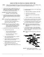
3.  Assemble saddle tapping valve assembly on pipe. 


a.  Turn Valve handle to expose lance beyond 

rubber gasket no more than 3/16”. 


b.  Place Valve Saddle against pipe.  Make sure 

lance fits into hole. 


c.  Hold Back Plate in a position directly opposite 

Valve Saddle. 

 
d.  Install screws far enough so Valve Saddle and 

Back Plate are held firmly against pipe.   


e.  Tighten screws evenly (brackets must be 

parallel). Tighten each screw firmly.  Do not crush 
pipe. 


4.  Connect source water tubing to valve housing using 

compression fitting (See Page 2, Step 4). 

 
5.  Connect tubing from saddle tapping valve to Filtration 

Module inlet elbow (Item 8 on Page 10, Figure 10). 

 
6.  Turn saddle tapping valve handle clockwise until it is 

firmly seated and piercing lance is fully extended. 


NOTE:

  Supply line is pierced and valve is closed. 

Do not open valve until system is activated  
(Page 11).


7.  Turn on cold water supply.  Check saddle tapping 

valve installation for leaks.  Allow water to run from 
faucet for a few minutes to clear any debris in the line 
caused by installation. 


NOTE:

  If flow from sink faucet is reduced, clean faucet 

aerator. 


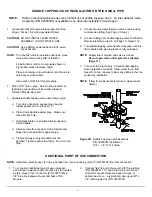
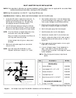
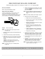
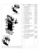
Figure 3B

  Saddle Tapping Valve Assembly  

   P/N 

34900001 

installed 

on 


7/16” – 1/2” O.D. Tubing 


ADDITIONAL POINT OF USE CONNECTION 


NOTE:

  Icemakers typically use 1/4" tubing as feed line.  Use a reducing union (P/N 33501043) for this connection.   


1.  To connect an additional point of use (icemaker, 

extra faucet in wet bar and/or another use for treated 
water), place a "tee" connector (P/N 33501040) in 
3/8" blue line between faucet and back of RO 
Module. 

2.  Connect "tee" to point-of-use with 3/8" blue tubing 

(P/N 60602001).  Connect tubing to point-of-use.  
Connector requirements are based on type of 
delivery device i.e., a typical icemaker uses 3/8" x 
1/4" reducing device (P/N 33501043)

Summary of Contents for 10401

Page 1: ...OWNER S GUIDE NSFR AQUAFIER ADVANCED ACTIVATED CARBON WATER TREATMENT SYSTEM Model Series 10401 10402 10403 Hydrotech Inc 25555 West Avenue Stanford Valencia CA 91355 661 294 8888 FAX 661 294 8880...

Page 2: ...OR The optional Smartap Monitor indicates filter cartridge status by measuring the volume of water passing through the Aquafier Water Treatment System When water is dispensed it flows through the syst...

Page 3: ...Quality Monitor Pushbutton Smartap Water Quality Monitor Module Only No Monitor Product Water Faucet Chrome or Stainless Steel Polymer Plain Front or with Light Bar Page I Table A Page 7 Fig 7 Page 9...

Page 4: ...are access to cold water supply line and to household sink Specific requirements are detailed in Table 1 PRODUCT WATER FAUCET FILTRATION MODULE Faucet may be installed in any convenient location Make...

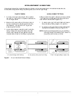
Page 5: ...cause the tubing to flex and deform which reduces its flow capacity and may increase lateral stress on the fittings causing leaks QUICK CONNECT FITTINGS Fittings consist of two parts a Body and a colo...

Page 6: ...side projections 1 2 or larger tubing use V side of bracket See Figure 3B b Hold Valve Saddle against tubing in a position directly opposite Back Plate c Install screws far enough so Saddle and Back...

Page 7: ...nst pipe e Tighten screws evenly brackets must be parallel Tighten each screw firmly Do not crush pipe 4 Connect source water tubing to valve housing using compression fitting See Page 2 Step 4 5 Conn...

Page 8: ...6 7 and 8 EXISTING COLD WATER SUPPLY VALVE COLD WATER LINE TO SINK 4 Insert rubber washer Item 1 into inlet adapter Item 2 and install adapter onto supply valve Align outlet hole in side of adapter t...

Page 9: ...htly Insert pilot guide into pilot hole Push down gently on drill motor to apply light pressure to porcelain surface Start drill motor turning as slowly as possible After initial cut has started motor...

Page 10: ...e washer are in place above sink Items 2 3 and 4 Optional Faucet Smartap Verify faucet body metal faucet base washer light bar base washer light bar assembly and washboard gasket are in place above si...

Page 11: ...Handle Faucet Body Faucet Stainless Steel Washer Faucet Base Stainless Steel Washer Rubber Faucet Base Washer Slotted Washer Faucet Nut Faucet Connector Faucet 3 8 x 7 16 Kit Rebuild Faucet Stainless...

Page 12: ...g nut by hand so that faucet does not move Do not over tighten NOTE Faucet is packaged for right hand operation For left hand operation realign knob by completing Step 5 NOTE Item callouts in Step 5 r...

Page 13: ...designates faucet body with plain front Code 1 designates faucet body with 1 LED Code 2 designates faucet body with 2 LED Code 3 designates faucet body with 3 LED Example 40303935 is a Faucet Body Ass...

Page 14: ...lel Cross over O Ring Port Retainer Plug Port Retainer Plug Switch Housing O Ring Switch Housing Plug O Ring Cartridge Activator Smartap Flow Monitor Sending Unit Flow Switch Spring Flow Switch Magnet...

Page 15: ...Gap Faucet Part Number Stainless Steel Faucet Only Stainless Steel with Light Bar 40301007 11702002 Chrome Faucet Only Chrome with Light Bar 40301002 11702001 Polymer Plain Front Polymer Light Bar 114...

Page 16: ...ACH WILL DAMAGE PLASTIC AND RUBBER COMPONENTS Rinse all parts that contact bleach thoroughly with clean potable water CAUTION Read the WARNINGS on the bleach container before using CAUTION Handle sani...

Page 17: ...y The connection to the battery is a snap type connector See Figure 11 20 Remove the battery by sliding it out of its holder 21 Replace the battery with a new alkaline 9 volt transistor battery P N 31...

Page 18: ...hes Lube and Reseat O Ring Replace O Ring Leak at saddle tapping valve Loose clamp Tubing deformed Tighten clamp screws do not crush source water tubing Cut damaged area off of tube or replace tube an...

Page 19: ...D SERVICED BY COMPANY SERVICE PERFORMED CLEANING ONLY CLEANING SANITIZING REPAIR FILTERS REPLACED CARBON Pb1 LEAD CARBON 5s VOC s COMMENTS DATE SERVICED SERVICED BY COMPANY SERVICE PERFORMED CLEANING...

Page 20: ...eet Hydrotech specifications If the drinking water system is altered by anyone other than Hydrotech the warranty shall be void ALL IMPLIED WARRANTIES INCLUDING WITHOUT LIMITATION WARRANTIES OF MERCHAN...

Reviews: