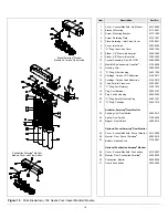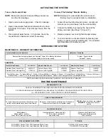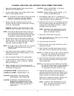
INTRODUCTION
NSF
R
THIS GUIDE IS APPLICABLE TO ALL AQUAFIER
®
MODELS
TABLE A
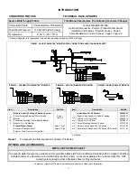
SYSTEM CONFIGURATION
FAUCET TYPE
Filtration Unit
Flow Monitor
Chrome
Stainless or Polymer
None
Faucet Smartap
®
10403002
10403102*
10402102*
Pushbutton Smartap
®
10403001 10403101* 10402101*
Aquafier
®
4 Vessel
Unitary Manifold
None 10401000
10401100* 10402100*
* System Tested and Certified By NSF International Against ANSI/NSF 53 and ANSI/NSF 42.
CERTIFIED CONTAMINANT REDUCTION PERFORMANCE
SYSTEM TESTED AND CERTIFIED BY NSF INTERNATIONAL AGAINST ANSI/NSF 53 AND ANSI/NSF 42 FOR REDUCTION OF
ASBESTOS LEAD
PARTICULATES CYSTS*
TURBIDITY
AESTHETICS: TASTE, AND ODOR CHLORINE REDUCTION CLASS I VOLATILE ORGANIC CHEMICALS (VOC's)
* Certification for reduction of Cysts including Cryptosporidium parvum ococysts and cysts of Giardia and Entamoeba.
SYSTEM STATISTICS
SYSTEM CAPACITY
without Smartap
®
Flow Monitor
SYSTEM CAPACITY
with Smartap
®
Flow Monitor
SERVICE FLOW RATE
at the Manifold Unit Outlet
3969 Litres (1050 gallons)
6615 Litres (1750 gallons)
1.9 Liters/minute (0.5 Gallons/minute)
PERFORMANCE INDICATOR
SMARTAP
®
WATER FLOW MONITOR
The optional Smartap
®
Monitor indicates filter cartridge status by measuring the volume of water passing through the
Aquafier
®
Water Treatment System. When water is dispensed, it flows through the system actuating the monitor and
recording the elapsed time for each dispense. Monitor indication is based on the cumulative number of gallons passed
through the system (elapsed time multiplied by flow rate). A green light indicates filters are functioning normally.
A yellow light indicates filters are nearing useful capacity and should be replaced.
Disconnecting the battery from the clip resets the Monitor. Installing a new battery each time filter cartridges are replaced
ensures an accurate indication of system performance and a continuing supply of high quality drinking water.
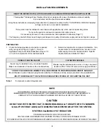
FAUCET ACTUATED SMARTAP
®
FLOW MONITOR
PUSHBUTTON ACTUATED SMARTAP
®
FLOW MONITOR
A light illuminates in a Light Bar each time a faucet
or additional point-of-use device is activated.
Light Bar Assembly is located at faucet base (Chrome or
Stainless Steel) or front of faucet body (Polymer).
Power is provided by nine volt alkaline battery.
A light illuminates when the test button is pressed.
Pushbutton Actuator and Indicator Lights
are located on the Manifold Cover.
Power is provided by nine-volt alkaline battery.
I


