background image

INSTRUCTIONS

www.Hydrofarm.com

4

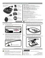
3.  To complete the base, connect End Rails (Part F) to each opposite side (see Image 3).  

NOTE: Be sure to install the Corner Legs V1 at two opposite corners from each other, and the 

Corner Legs V2 at the two remaining opposite corners. They must be installed this way or the 

assembly will be incorrect.

4.  Have a second person assist you in flipping the structure right side up to its original position. 

Now you can insert the Corner Retainers V1 and V2 (Parts H & I) (see Image 4). Place the Corner 

Retainers V1 at opposite corners and the Corner Retainers V2 at opposite corners)(see Figure 1 to 

see the proper relative angles of all four corner retainers at once). 

5.  Assemble the remaining 2-Piece Center Support Rails (Part G), locking them at proper length with 

their spring buttons, and center them over the Side Rails (Part B) (See Images 5 and 5a). 

Image 4

Image 5

Image 5a

Image 3

Summary of Contents for Active Aqua AASFT48

Page 1: ...INSTRUCTIONS AASFT48 AASLH48 AASLP48 UNIVERSAL TRAY STAND LARGE...

Page 2: ...Center Support Rail 2 H Corner Retainer V2 2 I Corner Retainer V1 2 J 2 Piece Center Leg Support Bar 1 Thank you for purchasing the Active Aqua Universal Large Tray Stand This stand supports Active Aq...

Page 3: ...ter Rail Top Part D on each side see Image 1 To connect your 2 Piece Center Leg Support Bar J first secure it at the proper length by locking it with the spring button Place the now partially assemble...

Page 4: ...on assist you in flipping the structure right side up to its original position Now you can insert the Corner Retainers V1 and V2 Parts H I see Image 4 Place the Corner Retainers V1 at opposite corners...

Page 5: ...humb Screws quantity 6 Group all of the stand parts together based on type for ease of locating and assembly i e corner legs together side rails together end bars together etc All parts will be marked...

Page 6: ...s Part A1 and lock them in place using Lynch Pins Part F1 see Image 8 5 Use the second pair of Lynch Pins Part F1 to adjust the height of the light hanger by inserting them into the appropriate holes...

Page 7: ...the End Rails Part F and Side Rails PartB by depressing the spring buttons and detach them from the Side Rails and End Rails 2 Replace the Corner Legs V1 Part A with the Low Profile Corner Legs V1 Pa...

Page 8: ...its ou autres en rapport avec le produit Certains tats n autorisent aucune limite concernant la dur e de la garantie implicite ou l exclusion des dommages fortuits ou cons cutifs les limites ou exclus...

Reviews: