background image

We set the wheels in motion.

®

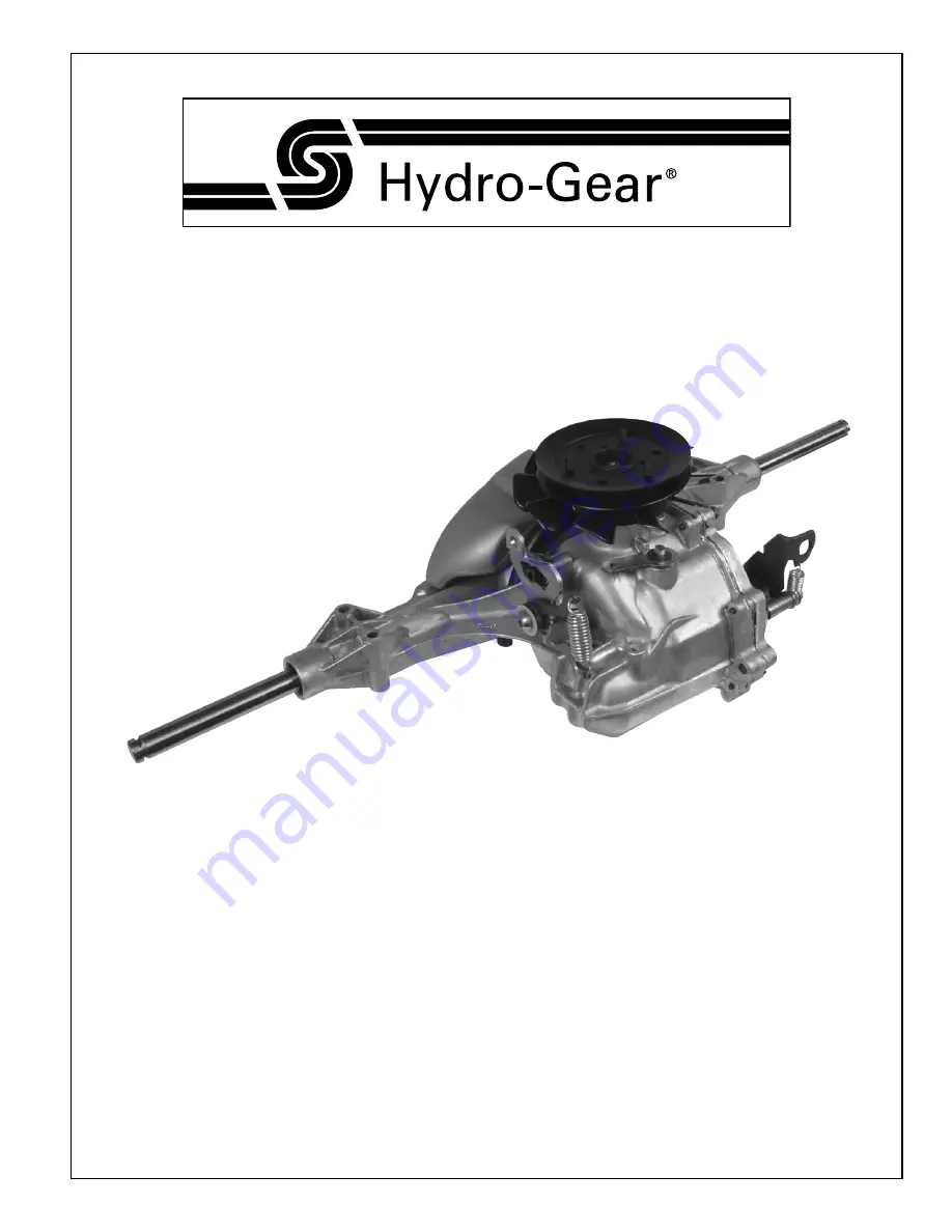
T2™

Integrated Hydrostatic Transaxle

Service and Repair Manual

BLN-52749

November 2006

Summary of Contents for T2

Page 1: ...We set the wheels in motion T2 Integrated Hydrostatic Transaxle Service and Repair Manual BLN 52749 November 2006 ...

Page 2: ...12 Brake Maintenance 13 Friction Pack Adjustment 13 Tear Down and Reassembly 14 How to Use This Manual 14 General Instructions 14 Tools 15 Torques 15 Transaxle Removal 16 Fan and Pulley 17 Expansion Tank 18 Control Arm Assembly 19 Return to Neutral Option 20 Brake Arm Brake Assembly 21 Side Housing 22 RH Axle Shaft 23 Bull Gear Set 24 Reduction Gear Set 25 Input Shaft 26 Swashplate 27 Bypass Arm 2...

Page 3: ... shop practice that your service area be equipped with the proper tools and the mechanics be supplied the latest information available All repair procedures illustrated in this guide are suggested but pre ferred methods of repair Internal repair procedures require that the transaxle unit be removed from the vehicle This is not a certification test or study guide for a certification test If a techn...

Page 4: ...l not require servic ing during the life of the vehicle in which it is installed Should other servicing be required the exterior of the transaxle will need to be thoroughly cleaned before beginning most procedures Do not wash the transaxle while it is hot Do not use a pressure washer to clean the unit GENERAL DESCRIPTION The T2 is a self contained unit designed for the transfer and control of powe...

Page 5: ...forced to turn with the flow of oil As the angle of the pump swashplate is increased the amount of oil being pumped will increase and cause a higher speed output of the motor Reversing the angle of the swashplate will reverse the direction of oil flow During the operation of the transaxle fluid is lost from the hydraulic loop through leak paths designed into the product for lubrication purposes ar...

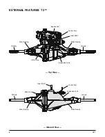
Page 6: ...S T2 Top View Inboard View Bypass Arm Oil Fill Plug Control Arm Input Shaft Main Housing Side Housing RH Axle LH Axle RH Axle LH Axle Expansion Tank Input Shaft Expansion Tank Side Housing Main Housing Control Arm Brake Arm ...

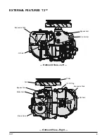
Page 7: ...T2 5 EXTERNAL FEATURES T2 Outboard View Left Outboard View Right Expansion Tank Bypass Arm Fan Pulley Brake Arm Brake Rotor RH Axle Oil Fill Plug Expansion Tank Control Arm Bypass Arm LH Axle ...

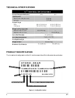
Page 8: ...f Product and Build Information Sales Drawing Number T2 TECHNICAL SPECIFICATIONS Overall Transaxle Reduction 20 6 22 7 Input Speeds Maximum Hi Idle No Load Minimum 3000 rpm 1800 rpm Output Torque Peak Continuous 395 lb ft 536 N m 105 lb ft 142 N m 425 lb ft 576 N m 115 lb ft 156 N m Weight on Tires per unit Maximum with 16 tires Maximum with 18 tires 540 lb 245 kg 500 lb 227 kg Axle Shaft Diameter...

Page 9: ...pment or the performance of your job Never allow untrained or unauthorized person nel to service or repair the equipment Wear appropriate clothing Loose or hanging clothing or jewelry can be hazardous Use the appropriate safety equipment such as eye and hearing protection and safety toe and slip proof shoes Never use compressed air to clean debris from yourself or your clothing TOOL SAFETY Use the...

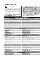
Page 10: ... Is Noisy Oil level low or contaminated oil Fill to proper level or change oil Page 10 Excessive loading Reduce vehicle loading Page 9 Loose parts Repair or replace loose parts Bypass assembly sticking Repair or replace linkage Page 9 Air trapped in hydraulic system Purge hydraulic system Page 11 Brake Partially Engage Disengage Brake Replace Broken or Missing Brake Return Spring Unit Has No Low P...

Page 11: ...t the bypass mechanism on the transaxle and vehicle linkage to insure it actuates and releases fully SERVICE AND MAINTENANCE PROCEDURES All the service and maintenance procedures presented on the following pages can be performed while the T2 is mounted on the vehicle Any repair procedures as mentioned in the repair section of this manual must be performed after the unit has been removed from the v...

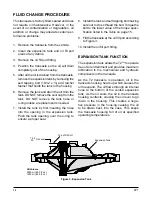
Page 12: ... a proper seal 8 Install the tank and self tapping bolt making sure not to cross thread the bolt Torque the bolt to the lower value of the torque speci fication listed in the Table on page 15 9 Fill the transaxle at the oil fill port according to Figure 3 10 Install the oil fill port fitting EXPANSION TANK FUNCTION The expansion tank allows the T2 to operate free of air entrainment and provides ma...

Page 13: ...starting make sure the transaxle trans mission is at the proper oil level If it is not fill to the specifications outlined on page 9 The following procedures should be performed with the vehicle drive wheels off the ground then repeated under normal operating condi tions 1 With the bypass valve open and the engine running slowly move the directional control in both forward and reverse directions 5...

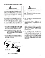
Page 14: ...ent Manufac turer s OEM s control linkage at the control arm Refer to Figure 4 WARNING Do not attempt any adjustments with the engine running Use extreme caution while inspecting all vehicle linkage Follow all safety procedures outlined in the vehicle owner s manual 3 Start the engine and increase the throttle to full engine speed 4 Check for axle rotation If the axles do not rotate go to Step 5 I...

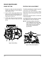
Page 15: ...riction pack dampens or holds the operator control lever in its desired position Adjustment for the amount of drag or holding force can be made by turning the friction pack nut in or out Adjustments should be made in no more than 1 4 turn increments Over tightening will result in difficulty or inability of the operator to move the control lever NOTE The factory setting for the friction pack is tig...

Page 16: ...re beginning any repairs Upon removal it is recommended that all seals O rings and gaskets be replaced During installation lightly lubricate all seals O rings gaskets with a clean petroleum jelly prior to assembly Also protect the inner diameter of seals by covering the shaft with a cellophane plastic wrap etc material Be sure all rem nants of this covering are removed after ser vicing Parts requi...

Page 17: ... 525 700 in lbs 59 3 79 1 Nm Center section bolt 24 Check plug 280 400 in lbs 31 6 45 2 Nm Check plugs 25 Check plug 280 400 in lbs 31 6 45 2 Nm Check plugs 41 TWHCS 5 16 18 x 1 230 310 in lbs 25 9 35 0 Nm Trunnion arm screw 43 Screw set 5 16 24 x 2 50 135 155 in lbs 15 2 17 5 Nm Control arm stud 49 Nut hex 5 16 24 nylon insert 85 120 in lbs 9 6 13 5 Nm Friction Pack Nut 127 HFHCS 1 4 20 x 2 0 w p...

Page 18: ...following procedures are pre sented in the order recommended for a complete tear down of the transaxle Figure 7 T2 Transaxle TRANSAXLE REMOVAL Do not disassemble the unit any far ther than necessary to accomplish the required repairs Reassembly is accomplished by per forming the Assembly portions of the procedures If the unit has been com pletely disassembled a summary of the assembly procedures i...

Page 19: ...5 for the required torque values NOTE As a general rule use the low end of the torque specification on fasteners when reassembling the unit Refer to Figure 9 FAN AND PULLEY CONFIGURATION 1 Remove the locknut 152 and washer 153 2 Remove the fan 150 and the pulley 151 Inspection 1 Check all components for wear or damage Replace if necessary Assembly 1 Reassemble all parts in the reverse order of dis...

Page 20: ... need to be removed unless replacing 4 Remove the screw 144 from the expansion tank 5 Remove the tank 143 Do not remove the hose 141 at this time Inspection 1 Inspect all parts for wear or damage Re place if necessary Assembly 1 Reassemble all parts in the reverse order of disassembly 2 When tightening the fasteners refer to the table on page 15 for the required torque values NOTE As a general rul...

Page 21: ... washer 46 and the plastic washer 45 4 Remove the Torx head screw 41 and dis card 5 Remove the control arm 42 the second washer 45 the belleville washer 44 and and the set screw 43 Inspection 1 Inspect all parts for wear or damage Re place if necessary 13 49 46 46 48 45 47 41 45 42 44 110 Assembly 1 Reassemble all parts in the reverse order of disassembly 2 When tightening the fasteners refer to t...

Page 22: ...if damaged or worn or if doing a complete disas sembly Refer to Seal Kit in the Items List on page 36 Inspection 1 Inspect all parts for wear or damage Re place if necessary Assembly 1 Reassemble all parts in the reverse order of disassembly 2 When tightening the fasteners refer to the table on page 15 for the required torque values 3 Install new Torx head screw 41 and lip seal 110 from seal kit N...

Page 23: ...25 from the brake yoke 124 7 Remove the brake rotor 121 the inner puck 120 and the seal 7 and discard NOTE Only remove the seal 7 if damaged or worn or if doing a complete disas sembly Refer to Seal Kit in the Items List on page 36 Inspection 1 Inspect all parts for wear or damage Re place if necessary Assembly 1 Reassemble all parts in the reverse order of disassembly 2 When tightening the fasten...

Page 24: ...e 14 Side Housing Removal Assembly 1 Reassemble all parts in the reverse order of disassembly 2 Apply a bead of sealant around the perim eter of the main housing face See Sealant Application Diagram on page 33 3 Align the side housing 2 with the main housing 1 Use care not to smear the seal ant bead 4 Install the ten housing screws 8 Refer to the screw tightening pattern on page 34 5 When tighteni...

Page 25: ...ow 6 Remove the inner bushing 105 Inspection 1 Inspect the axle shaft for wear or damage Replace if necessary Assembly 1 Assemble items in reverse order of disas sembly NOTE To protect the lip seal from possible damage when installing into the bore and over the axle shaft apply a protec tive covering over the splines sharp corners and or keyway of the axle shaft e g cellophane tape etc Remove prot...

Page 26: ...er gears 102 with two differential pins 108 and bull gear 107 Inspection 1 Inspect all items of the bull gear set for wear or damage BULL GEAR SET Assembly 1 Reassemble all parts in the reverse order of disassembly 2 Install the bull gear 107 3 Install the miter gears 102 with the differ ential pins 108 Figure 16 Bull Gear Set 107 108 102 102 108 1 ...

Page 27: ... 3 Remove the jack shaft 92 and second washer 93 Inspection 1 Inspect all items of the reduction gear set for wear or damage Assembly 1 Reassemble all parts in the reverse order of disassembly 2 Install the washer 93 and jack shaft 92 3 Install the jack shaft gear 91 into the re duction gear 90 Insert onto the jack shaft 92 4 Place the washer 93 onto the jack shaft 92 Figure 17 Reduction Gear Set ...

Page 28: ...e the bearing 62 from the pump shaft 61 Inspection 1 Inspect the bearing and input shaft for wear or damage Inspect the splines on the shaft for possible damage Replace if neces sary Figure 18 Input Shaft Assembly 1 Reassemble all parts in the reverse order of disassembly 2 Install the bearing 62 a new retaining wire 63 and spring 67 onto the input shaft NOTE Apply a light coating of grease to new...

Page 29: ...ring 74 from the swashplate 40 and set aside Inspection 1 Inspect the swashplate 40 and thrust bearing assembly 74 for wear or damage Replace if necessary 2 Inspect pump block per detail on page 30 Assembly 1 Reassemble all parts in the reverse order of disassembly 2 Apply a light coating of oil to running sur faces on center section swashplate bearing races thrust bearing assembly and pump block ...

Page 30: ...ass rod 32 unless it is damaged or worn 5 Remove the lip seal 30 and discard Inspection 1 Inspect the bypass rod 32 for wear or dam age Replace if necessary NOTE Take care to insure that the bypass rod is free of burrs that may cut the rubber lip seal 2 Inspect the housing bore Assembly 1 Reassemble all parts in the reverse order of disassembly 2 Install a new lip seal 30 3 Install the bypass rod ...

Page 31: ... Inspect motor cylinder block assembly 75 per detail on page 30 5 Inspect the bearing surfaces in the main housing Assembly 1 Reassemble all parts in the reverse order of disassembly 2 Apply a light coating of oil to all running surfaces 3 Place the thrust bearing assembly 79 into the main housing Position so the thick race will contact the motor block pistons 4 Insert the motor shaft assembly 82 ...

Page 32: ...der block compo nents set aside until ready for installation of the center section and swashplate Refer to pages 27 and 29 Refer to Figure 23 Disassembly 1 Remove the magnet 28 and the filter 27 The filter can be removed without damaging the filter base 2 Remove the deflector 29 3 Inspect the check plugs 24 25 Remove if necessary 4 Inspect the filter base 26 Remove replace if necessary Inspection ...

Page 33: ...ow 6 Remove the inner bushing 105 Inspection 1 Inspect the axle shaft for wear or damage Replace if necessary Assembly 1 Assemble items in reverse order of disas sembly NOTE To protect the lip seal from possible damage when installing into the bore and over the axle shaft apply a protec tive covering over the splines sharp corners and or keyway of the axle shaft e g cellophane tape etc Remove prot...

Page 34: ...ansion tank fitting 140 Inspection 1 Inspect the fitting for damage and replace if necessary Assembly 1 Install the fitting into the main housing Refer to torque chart on page 15 2 Install a new O ring 142 onto the fitting 3 Place the expansion tank hose 141 onto the fitting 140 EXPANSION TANK HOSE AND FITTING Figure 26 Expansion Tank Hose and Fitting 141 142 140 ...

Page 35: ... the reduction gear set See page 25 8 Install the bull gear set See page 24 9 Install the RH axle assembly See page 23 Figure 27 Sealant Application Diagram ASSEMBLY AFTER A COMPLETE TEAR DOWN 10 Apply sealant to the main housing prior to assembly with the side housing See page 33 NOTE Prior to applying the new sealant the old sealant must be removed from all surfaces A small consistent bead appro...

Page 36: ...quence Starting with the number 1 screw location tighten sequentially through to 10 Torque each screw to 105 155 lb in 11 8 17 5 Nm NOTE As a general rule use the low end of the torque specification SIDE HOUSING SCREW TIGHTENING SEQUENCE ...

Page 37: ...5 124 128 109 110 106 103 108 22 152 153 150 151 152 153 150 151 107 105 140 35 49 46 48 47 46 45 45 44 43 42 165 166 162 164 168 166 160 162 167 169 44 161 163 75 79 23 201 25 24 93 90 91 92 93 82 81 80 93 29 27 26 28 83 42 41 34 33 32 31 30 66 65 64 62 61 1 67 40 74 70 63 101 100 202 106 110 109 110 142 146 145 143 147 144 ...

Page 38: ...linder 10cc 76 Piston 10cc 77 Spring Comp 10cc Piston 78 Washer Piston Seat 47 OD 79 Bearing Thrust Ball 30 x 52 x 13 80 Ring Retaining 50 External Motor Shaft part of 202 81 Gear 13T Pinion 82 Shaft Motor 83 Washer 60 x 1 00 x 03 90 Gear 11T 48T 91 Gear Jack Shaft 11T 92 Jack Shaft Pin 93 Washer 50 x 1 00 x 03 100 Ring Retainer included in Center Section Kit 202 101 Gear Bevel 12T Spline ID 102 G...

Page 39: ... in the charge circuit Check Valve A valve whose primary function is to restrict flow in one direction Closed Loop A sealed and uninterrupted circulating path for fluid flow from the pump to the motor and back Decay Rate The ratio of pressure decay over time End Cap See Center Section Entrained Air A mechanically generated mixture of air bubbles having a tendency to separate from the liquid phase ...

Page 40: ... of the components and allowing the air a path of escape Rated Flow The maximum flow that the power supply system is capable of maintaining at a specific operating pressure Scoring Scratches in the direction of motion of mechanical parts caused by abrasive contami nants Swash Plate A mechanical device used to control the displacement of the pump pistons in a fluid power system System Charge Check ...

Page 41: ...T2 39 NOTES ...

Page 42: ...40 T2 NOTES ...

Page 43: ......

Page 44: ... 2006 HYDRO GEAR Printed in U S A Rev P ...

Reviews: