


SERVICE MANUAL
XL-S10H
No. S2406XLS10H//
MICRO COMPONENT SYSTEM
XL-S10H
MODEL
SHARP CORPORATION
CONTENTS
This document has been published to be used
for after sales service only.
The contents are subject to change without notice.
CHAPTER 1. GENERAL DESCRIPTION
[1] SAFETY PRECAUTION FOR SERVICE
MANUAL .......................................................1-1
ONLY)............................................................1-1
[1] ADJUSTMENT ..............................................2-1
[2] TEST
MODE .................................................2-2
[3] When the CD does not function ....................2-3
CHAPTER 3. MECHANICAL DESCRIPTION
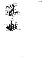
[1] DISASSEMBLY .............................................3-1
DIAGRAM.........................................4-1
CHAPTER 5. CIRCUIT DESCRIPTION
[1] VOLTAGE ......................................................5-1
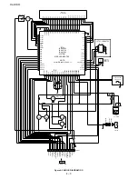
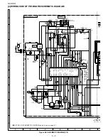
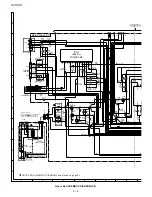
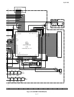
CHAPTER 6. CIRCUIT SCHEMATICS AND PARTS
LAYOUT
[1] NOTES ON SCHEMATIC DIAGRAM ............ 6-1
[2] IC701 SERIAL No. TABLE ............................. 6-1
[3] TYPES OF TRANSISTOR AND LED ............ 6-1
[4] WIRING SIDE OF P.W.BOARD/SCHE-
MATIC DIAGRAM .......................................... 6-2
[1] FUNCTION TABLE OF IC.............................. 7-1
[2] LCD
DISPLAY ................................................ 7-3
[3] WIRING OF PRIMARILY SUPPLY LEADS
(FOR U.K. ONLY) .......................................... 7-4
XL-S10H Micro Component System consisting of XL-
S10H (main unit) and CP-S10H (speaker system).
•
In the interests of user-safety the set should be restored to its origi-
nal condition and only parts identical to those specified be used.
•
Note for users in U.K.
Recording and playback of any material may require consent which
SHARP is unable to give. Please refer particularly to the provisions
of Copyright Act 1956, the Dramatic and Musical Performers Pro-
tection Act 1956, the Performers Protection Acts 1963 and 1972
and to any subsequent statutory enactments and orders.
(Except for U.K.)


