25
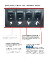
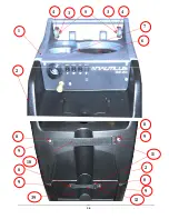
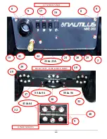
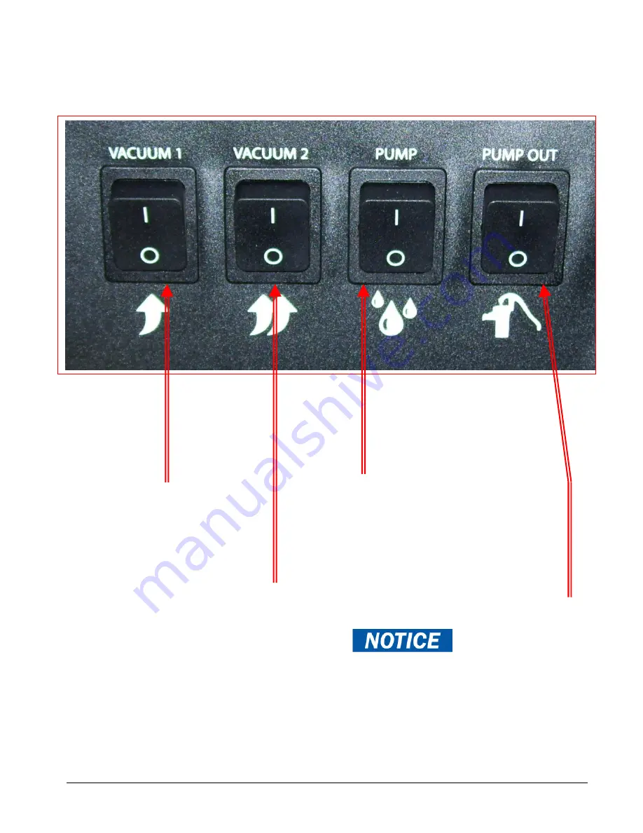
NAUTILUS EXTREME MXE-200 SWITCH PANEL:
(Shown with optional Pump-Out)
Vacuum #2 – Power from Cord #2.
When the switch is turned to the ON position
power is supplied to the vacuum motor.
(3-Stage Vacuum)
Solution Pump Switch – Power from Cord #1
.
When the switch is turned to the ON position
power is supplied to the solution pump motor.
When not using solution (Extracting Only) do not
turn this switch ON.
OPTIONAL - Waste Pump Switch
Power from Cord #2.
Do not turn Waste Pump
Switch ON unless a hose is connected to the Pump-
out Outlet port.
If the Float switch is down the pump will not turn
on when the switch is turned on. When the water
level gets high enough the Float switch will turn the
waste pump on and off again when the level drops.
Vacuum #1 – Power from Cord #1.
When the switch is turned to the ON
position power is supplied to the vacuum
motor. (3-Stage Vacuum)
Cooling Fans – Power from Cord #1.
The two cooling fans are not controlled by
any switch.
As soon as Cord #1 is plugged in the
cooling fans will turn on to exhaust air from
the base.
Summary of Contents for Nautilus Extreme MXE-200
Page 1: ...1 LMANN20 Revised 02 16 2018 Nautilus MXE 200 Operating Manual EXTREME ...
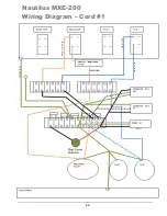
Page 23: ...23 M1200 Wiring Diagram Nautilus MXE 200 Wiring Diagram Cord 1 ...
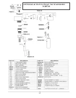
Page 37: ...37 OPTIONAL AUTO FILL FLOAT VALVE ASSEMBLY NM5740 ...
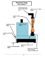
Page 38: ...38 Pump Out Pump PARTS ASSEMBLY ...
Page 39: ...39 1 4 4 6 7 8 9 10 11 3 3 8 9 12 8 9 39 8 9 2 2 5 ...
Page 49: ...49 92 91 95 94 112 13 14 14A 104 105 1 39 PUMP OUT CONNECTIONS ...
Page 50: ...50 35 36 36A 78 36 36A 34 39 127 128 129 2 1 130 32 34 119 39 131 ...

