3.4
BLADE BRUSH ADJUSTMENT
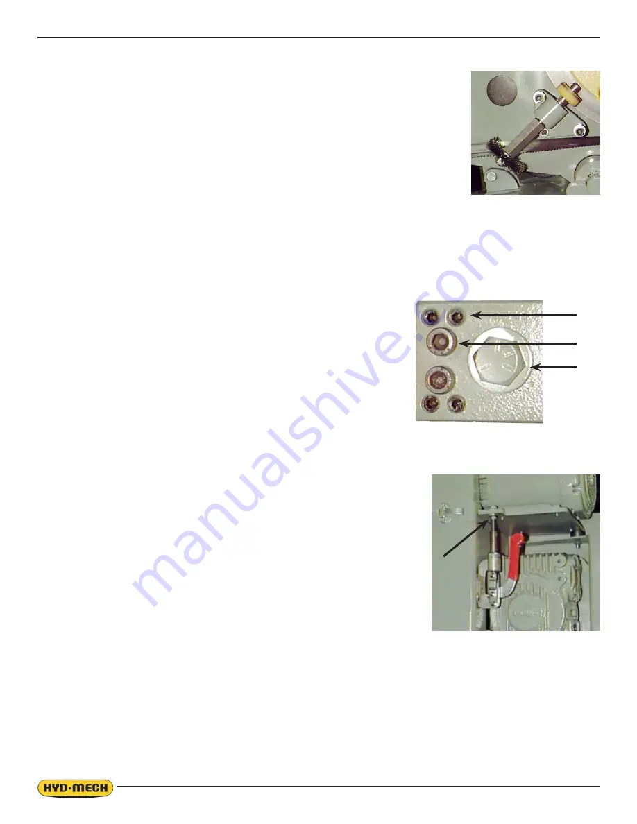
The machine leaves the factory with the blade brush adjusted for maximum life of the
brush. This setting places the ends of the blade brush wires so as to contact the blade at
the bottom of the blade gullets. The plastic drive wheel that is driven by the drive wheel
face should be held against the blade face with the minimum force that is necessary. As
the blade brush wears it is necessary to periodically adjust it closer to the blade or if a new
brush is installed, further away from the blade.
As shown, there are two springs on socket head screws holding the brush assembly against
the blade. There is also an adjusting socket set screw with a hex nut on it. Loosen the hex
nut with a 9/16” wrench and turn the setscrew counter clockwise with a 3/16” Allen key. This
will move the brush closer to the blade. Adjust the setscrew so that the brush cleans to the
bottom of the blade gullets and tighten the hex nut.
ANGLE BRAKE ADJUSTMENT
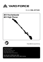
The clamping force on the swivel brake can be adjusted to ensure that the Head is held securely and does not move
GXULQJFXWWLQJ7KHEUDNHKDQGOHVKRXOGEHDGMXVWHGVRWKDWLWGRHVQRW³ERWWRPRXW´RUKLWLWVPRYHPHQWOLPLW\HWKROGWKH
head securely.
ANGLE BRAKE ADJUSTMENT PROCEDURE:
6WHS±/RRVHQORFNLQJFDSVFUHZV³%´ZLWKDó$OOHQNH\
6WHS±7LJKWHQDOOVHWVFUHZV³$´XQWLOVQXJZLWKD$OOHQNH\
6WHS±%DFNRXWWKH³$´VFUHZVóWXUQ
6WHS±7LJKWHQWKHORFNLQJFDSVFUHZV³%´
Step 5 – Swing the head to 45
q
and back to ensure that the head moves freely
and does not bind on the pivot surfaces. Continue to step 6 if necessary.
6WHS±$GMXVWWKHFODPSLQJIRUFHEROW³&´ZLWKDô´ZUHQFK,IQRWWLJKWHQHG
HQRXJKWKHORFNLQJKDQGOHZLOO³ERWWRPRXW´DQGQRWKROGWKHKHDG¿UPO\
BELT TENSION ADJUSTMENT (Not applicable to S23)
Drive belt tension is maintained by the locking of a toggle clamp assembly. The
release of the toggle clamp permits the drive belt to be loosened so that the blade
speed can be changed by selecting a different pulley ratio.
1. Stop the blade motor. Undo the cover latch and swing the pulley cover
away.
2. At the midpoint between pulleys, you should be able to push the belt in ½”.
Too much or too little movement will cause slippage or abnormal wear on
the belt and other drive system parts.
3. If adjustment is needed, loosen the lock nut with a 9/16” wrench and turn
the adjusting bolt until the belt tension is set.
4. Tighten the lock nut. Test the belt on all speeds, and then close the cover.
A
B
C
Summary of Contents for S-20
Page 2: ......
Page 18: ......
Page 26: ......
Page 34: ......
Page 42: ......
Page 43: ...5 1 SECTION 5 HYDRAULIC FOR HYDRAULIC SCHEMATICS AND PLUMBING DIAGRAMS SEE PDF ON ATTACHED CD ...
Page 44: ......
Page 45: ...6 1 SECTION 6 MECHANICAL ASSEMBLIES For Mechanical Assembly Drawings see PDF on attached CD ...
Page 46: ......
Page 52: ...8 2 S20 CUTTING CAPACITY ...
Page 53: ...8 3 S20 MACHINE LAYOUT SHEET 1 ...
Page 54: ...8 4 S20 MACHINE LAYOUT SHEET 2 ...
Page 56: ...8 6 S23 CUTTING CAPACITY ...
Page 57: ...8 7 S23 MACHINE LAYOUT SHEET 1 ...
Page 58: ...8 8 S23 MACHINE LAYOUT SHEET 2 ...
Page 60: ......


