background image

MEP S.p.A.

7--2

Use and maintenance manual DM 8

Topping up and bleeding the cylinder (Cut Control System)

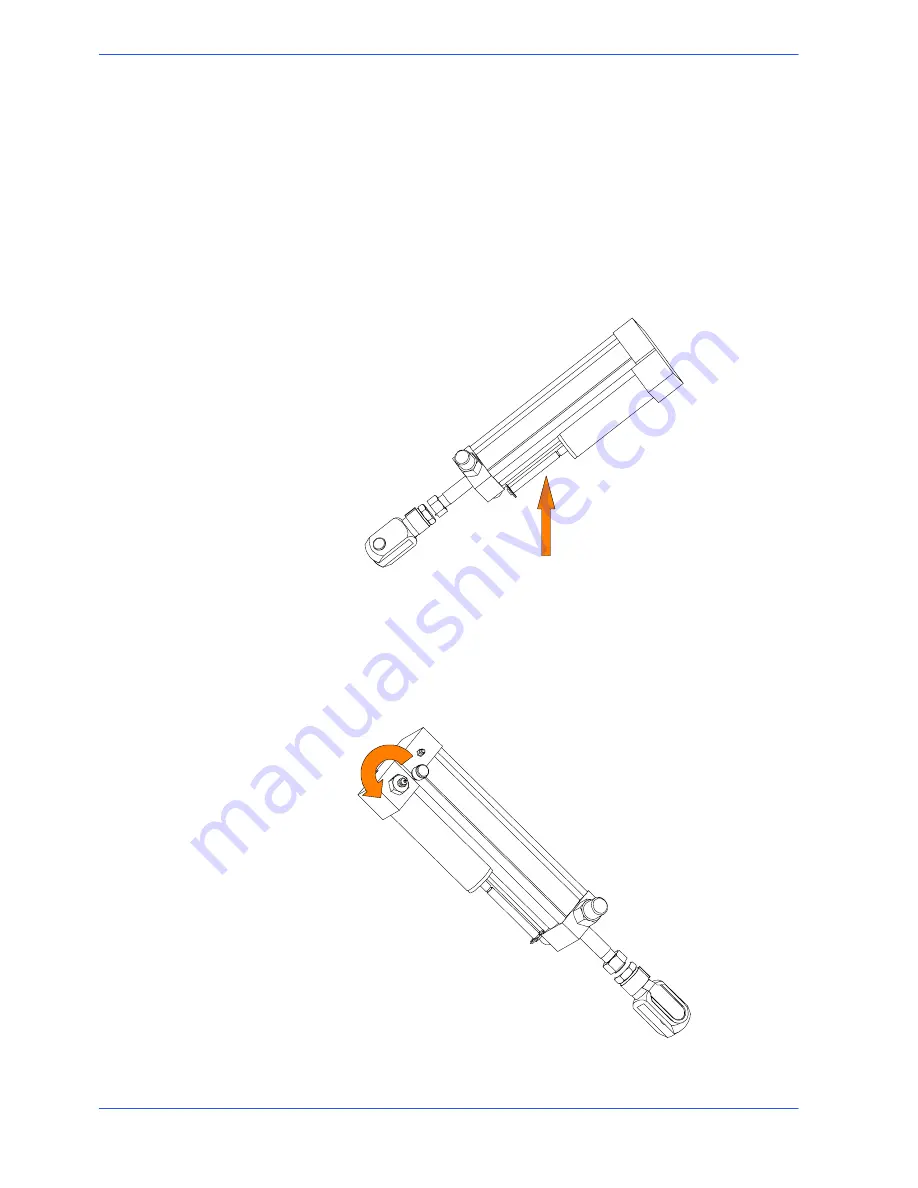
Topping up the head cylinder

This operation is done when the oil in the hydraulic cylinder compensator tank is

low.
First the cylinder head is brought to the HUL (Head Up Limiter) position so that

the oil level in the compensation tank (see photograph below) can be checked

using the rod. If the rod upper ring location is not visible, the oil level is insuffi-

cient.

To top up the oil in the tank, the instructions are as follows:

"

keep the head in the HUL position (fully up) by closing the head descent reg-

ulator;

"

unscrew the filler valve cap;

Summary of Contents for DM8

Page 1: ...CA YEAR OF MANUFACTURE ______________ USE AND MAINTENANCE MANUAL DM 8 ...

Page 2: ......

Page 3: ...hine noise levels 3 8 Electromagnetic compatibility 3 9 Emissions 3 9 Immunity 3 10 Machine installation 4 1 Packaging and storage 4 1 Anchoring the machine 4 4 Minimum requirements 4 4 Check list 4 5 Optionals to be requested with original order 4 5 Optionals 4 5 Balancing the cutting head 4 6 Connection to the compressed air supply MA version 4 6 Connection to the power supply 4 7 Description of...

Page 4: ... terminals 6 30 Standard version electrical diagram 220V Single Phase CSA standard 6 31 List of cables 6 35 List of components 6 38 List of terminals 6 39 Exploded views 6 40 Motor assembly 6 40 Front flywheel assembly 6 42 Motor flywheel assembly 6 44 Cutting head cover 6 46 Vice assembly 6 48 Base assembly 6 50 Control panel 6 52 Handgrip 6 54 Reduction gear 6 56 Fixed work table and turntable 6...

Page 5: ...trol System hydraulic circuit 8 3 Oil for transmission box 8 3 Oil for lubricant coolant fluid 8 4 Cutting speed and choice of tools 9 1 Cutting speed 9 1 Standard machine 9 1 Machine with 4 8 pole motor optional 9 1 Machine with Inverter optional 9 1 Choice of blade 9 2 Saw tooth pitch 9 3 Cutting speed and downstroke speed 9 3 Lubricant coolant fluid 9 4 Blade structure 9 5 Blade types 9 5 Blade...

Page 6: ......

Page 7: ...igh cutting capacity which enables it to handle both single workpieces and bundles combined with the possibility of making inclined cuts from 60 left to 45 right make this model the ideal solution for satisfying the wide strange of cutting needs of machine shops turneries structural steel shops and engineering workshops We congratulate our clients on having chosen this product which will give effe...

Page 8: ...d the head commences its downstroke the speed of which can be adjusted using the control valve head downstroke speed regulator located on the control panel The head performs the cutting operation once the cut has been made a limiter stops the cutting cycle after which the head is manually returned to its upper position so that when a new workpiece is in place a new cycle can be started using once ...

Page 9: ...0 Frequency 50 60 Hz 5 Output voltage Maximum voltage equal to the supply voltage Output frequency range 0 5 to 320 Hz Max transients 150 of electronic speed control rated current for 60 secs Frequency resolution Display 0 1 Hz Analog inputs 0 1 Hz per 100 Hz max Switching frequency Adjustable from 2 2 to 12 Hz max galvanic insulation between power and control panel Electronic speed control protec...

Page 10: ...0 32 Oil for Cut Control System cylinder capacity in Litres 0 7 Lubricant coolant fluid oil concentration 5 6 capacity in Litres 11 VICE Vice max opening mm in 275 10 83 SPINDLE MOTOR Three phase 2 4 pole asynchronous Frequency 60 Hz No of poles Current Volts Absorption Amps Power HP rpm Band saw speed 2 4 208 11 8 2 1 8 1 5 3150 1580 72 36 mt min 22 43 11 21 ft min 2 4 240 8 9 6 5 1 8 1 5 3480 17...

Page 11: ...ons 1 5 The machine is supplied with a 2 4 pole three phase motor giving 2 band saw speeds 1ª speed 4 poles 36 mt min 11 21 ft min 2ª speed 2 poles 72 mt min 22 43 ft min The OPTIONAL 4 8 pole motor gives speeds of 36 18 mt min 11 21 5 61 ft min Warning ...

Page 12: ...ng IP 55 Conforming to CEI norms publication IEC 34 of 01 07 1985 CUTTING CAPACITY Section Ø lxl bxh 0 210 mm 8 27 in 200 mm 7 87 in 270x200 mm 10 63x7 87 in 45 left 180 mm 7 09 in 180 mm 7 09 in 180x190 mm 7 09x7 48 in 60 left 100 mm 3 94 in 90 mm 3 54 in 120x90 mm 4 72x3 54 in 45 right 130 mm 5 12 in 130 mm 5 12 in 120x150 mm 4 72x5 90 in PACKED WEIGHT Wooden cage and pallet Kg 70 Wooden pallet ...

Page 13: ...duction and technical specifications 1 7 Dimensions MACHINE INSTALLED Work table height mm in 870 34 25 Weight Kg 430 900 700 470 410 550 170 1800 1830 870 1315 72 05 18 50 35 43 16 14 6 70 27 56 21 65 34 25 51 77 70 87 ...

Page 14: ...ds a full understanding of how the machine works which is described in detail in the chapter DESCRIPTION OF MA CHINE OPERATION this chapter deals with the main units and their locations CUTTING HEAD VICE CONTROL PANEL BASE TURNTABLE 2 Functional parts ...

Page 15: ...ork table and its cutting stroke is manually guided by the operator Handwheel Blade guide head plate Handgrip Blade guide heads Head joint pivot Transmis sion box Motor Vice The vice is the unit that clamps the workpiece in place during cutting it consists of a vice support commonly known as a lead nut fixed to the work table and a lead screw with a slideway on which the mobile jaw is mounted The ...

Page 16: ...entional interference with the unit In order to remove the panel from its mounting the main switch has to be shifted to 0 OFF which automatically cuts off the electrical supply Panel fastened by screws Control panel Main switch Turntable A cast iron casting forms the fulcrum for the cutting head and the support for the work table and the control panel Releasing the locking lever on the slideway al...

Page 17: ...anual DM 8 Base On opening the door in the base you will find the air treatment unit optional extra only on versions with MA automatic vice and the drawer with the coolant complete with electric pump Lubricant coolant tank Electric pump ...

Page 18: ...nings and accident prevention standards in this manual must be respected without question by all those concerned with the operation of the machine The following definitions are those provided for by EC DIRECTIVE ON MA CHINERY No 98 37 CE Danger zones any zone in and or around a machine in which the presence of a person constitutes a risk for the safety and health of that person Person exposed any ...

Page 19: ...so avoiding any blinding light concentrations Reference standard ISO 8995 89 Lighting in work environments CONNECTIONS Check that the power supply cables and pneumatic feed systems comply with the maximum machine absorption values listed in the Machine Specification tables replace if necessary GROUNDING The installation of the grounding system must comply with the requirements set out in IEC STAND...

Page 20: ...g working long hair must be tied back and bunched Before starting cutting operations support the material at both ends of the machine using the support arm standard or OPTIONAL accessories such as the feed and discharge roller tables shown in the diagram below FEED SIDE ROLLER TABLE 1500 mm 59 05 in DISCHARGE SIDE ROLLER TABLE 1500 mm 59 05 in Always disconnect the power supply to the machine befo...

Page 21: ...es that exceed the capacity of the ma chine as listed in the machine specifications Never move the machine while it is cutting Do not use blades of different sizes to those recommended in the ma chine specifications When cutting very short pieces make sure that they are not dragged be hind the support shoulder where they could jam in the blade When using the pneumatic vice MA version check that th...

Page 22: ...rotection and safeguarding the environment These standards have been incorporated in the DM 8 band saw Reference standards MACHINE SAFETY EEC Directive no 98 37 CE of 14 06 1989 known as Machines Directive EEC directive no 89 336 EMC Electromagnetic Compatibility EEC Directive no 73 23 known as Low voltage directive HEALTH AND SAFETY AT THE WORKPLACE EEC Directive no 80 1107 83 447 86 188 88 188 8...

Page 23: ...f 8 mm 0 31 in The jaw must be moved from 2 to 3 mm from the workpiece 5 2 1 6 4 3 Electrical equipment In accordance with Italian standard CEI 60204 1 April 1998 derived from European Standard EN 60204 1 December 1997 publication IEC 204 1 October 1997 access to electrical control panel limited by screws and panel lock device allowing panel to be opened only after the electricity supply has been ...

Page 24: ... the actuator must be rotated by 45 After the emergency situation has been resolved the machine must be reset 2 Automatic thermal magnetic cutout switch with thermal magnetic relay the machine auto switch located on the control panel has two protection systems against voltage drops In the case of a voltage drop all electrical components are disengaged the machine stops immediately and automatic re...

Page 25: ...meters and supplies one overall indication The Leq is based on the principle of equal energy and represents the continuous stationary level containing the same amount of energy expressed in dBA as the real fluctuating level over the same time period Machine noise levels Identification Machine Type Band saw for metal Model DM 8 Reference standard ISO 3746 Results T t 1 Description C 40 steel cut pi...

Page 26: ...by disturbances of defined magnitude The following text contains a list of the applied standards and the results of the electromagnetic compatibility testing of machine model DM 8 Test report no 061200 Emissions EN 50081 2 1994 Electromagnetic Compatibility Generic standard regarding emissions Part 2 Industrial Environment EN 55011 1999 Industrial scientific and medical radio frequency appliances ...

Page 27: ...l DM 8 Immunity EN 50082 2 1995 Electromagnetic Compatibility Generic standard on immuni ty Part 2 Industrial Environment The EUT is deemed to fulfil the immunity requirements without testing because it contains no electonic control circuitry ...

Page 28: ...a pallet with straps and heat shrink plastic on a pallet with straps heat shrink plastic and a wooden crate In both cases for correct balancing the machine must be handled using a fork lift truck inserting the tines at the points indicated by the arrows using the reference marks on the crate itself Before carrying out lifting operations make sure that the weight of the ma chine as indicated on the...

Page 29: ...e stacked two high and machines pallettized and crated must not be stacked three high To install the machine first remove the packing paying particular attention not to cut any electric wires or hydraulic hoses if necessary use pliers a hammer and a cutter Open crate in the illustrated order 1 remove nails and lift the top of the cage Attention Attention ...

Page 30: ... Machine installation 4 3 2 remove nails and lower walls 3 remove heat shrink covering 4 remove the straps 5 remove nails from pallet securing planks and remove planks 6 remove the front panel and insert fork tines ...

Page 31: ... taken into account when positioning the machine BASE seen from below Ø 12 mm 0 47 in 920 mm 36 22 in 480 mm 18 90 in 704 5 mm 27 74 in Ø 12 mm 0 47 in 704 5 mm 27 74 in Minimum requirements For the machine to function correctly the room in which it is to be installed must satisfy the following requirements power supply voltage frequency refer to the values on the rating plate Working pressure MA ...

Page 32: ...p protection 24 V low voltage plant blade protection behind and below blade guide heads precision stops for cuts at 0 45 60 left and 45 right Cut Control System CCS accessory kit The accessory kit bag is enclosed in the machine before packing the following is a list of the accessories hexagonal keys 4 10 mm pipe wrench 10 mm measuring rod for cuts to measure arm with roller predisposed for roller ...

Page 33: ...ad weight Using a 10 mm wrench tighten the screws until the distance between the first coil of the spring and the bracket is 8 mm 0 31 in Connection to the compressed air supply MA version The MA version automatic vice is supplied with an air treatment unit for the vice closing system controlled by a pneumatic cylinder To ensure perfect performance and long service life we advise that the machine ...

Page 34: ... S L2 T L3 CONNECTION FOR 4 CORE WIRE SYSTEMS WITH NEUTRAL PE GND When using systems with a neutral wire special care must be taken when con necting the blue neutral wire as if it is connected to a phase wire it will dis charge the phase voltage to the equipment connected for voltage phase neutral Insert the plug in the socket ensuring that the mains voltage is the same as that for which the machi...

Page 35: ...utton on the manual head control lever if all the above operations have been carried out correctly the blade motor will start up and the blade will start rotating Ensure that the blade moves in the correct direction as shown in the above figure If it does not simply reverse two of the phase wires on the ma chine power supply input The cutting machine is now ready to start the work for which it was...

Page 36: ...ol panel Description of the control panel The components of the DM 8 control panel are shown in the diagram below Each arrow has a number which corresponds to the descriptions that follow 2 1 3 5 4 1 LED STAND BY This either confirms machine start up or indicates an emergency state to the operator 5 Description of machine operation ...

Page 37: ... relay and the blade motor thermal magnet cutout This device has three protection systems against power failure When there is a power failure the electrical devices are all shut down instantly shutting down the machine and preventing automatic restoring of power on power return A further function is to reset the thermal relay which protects against overcurrents 4 POLARITY CHANGE SWITCH This select...

Page 38: ...nstalled in a housing blue knob sealed against external agents such as dust or moisture with a protection rating of IP 55 Basic instructions for carrying out a cutting operation cycle Manoeuvring the cutting head Cutting head movement is facilitated by perfect balancing of the head weight thanks to the traction force exerted by the two return springs located at the back of the machine Also the gri...

Page 39: ...lamping the work piece in the Automatic Vice MA version If the machine is equipped with the Automatic Vice optional device MA the opening and closing of the vice is performed by means of the manual valve switch located on the base which activates the vice pneumatic cylinder device An optional pedal unit is available as an alternative to the manual valve Near the vice from 2 to 3 mm from the work p...

Page 40: ...d in the photograph and rotate in a clockwise direc tion the vice is free to slide forwards and backwards into the desired position when the lever is released the vice blocks in that position Rapid translation of the vice For inclined cuts move the vice to the left or right sliding it on the sliding guide Loosen the locking lever as indicated in the figure position the vice to the right or left an...

Page 41: ...ed on the basis of the longitudinal section of the workpiece in order to leave free only the part of the saw which will perform the cut position the workpiece on the work table close to the blade vertical loosen the ratchet lever on the sliding shaft of the front blade guide head the mobile front guide head must be positioned near to the material leaving the downstroke trajectory free to reach bey...

Page 42: ... place and correctly locked the level of lubricant coolant and that the electropump is activated that the blade downstroke speed and the cutting pressure are correct version with CCS Manual operating cycle Sequence of operations for performing a cut power up the machine by pressing the reset button Position the workpiece in the vice and calculate the length of cut using the measuring rod for cuts ...

Page 43: ...rol lever and start the blade rotating by pressing the micro switch on the handgrip the downstroke speed of the head is manually con trolled by the operator The motor starts up and sets the blade in rotary motion the lubricant coolant pump starts up at the same time ...

Page 44: ...ece from the vice in the MA version the vice is opened using the open close button or by manually turning the vice handwheel If the machine is equipped with the Cut Control System make sure that the function selector switch is positioned on Manual and that the head return spring is tensioned in the Manual position Warning ...

Page 45: ...od Clamp the piece in the vice if the machine is the MA version bring the vice manually from 2 to 3 mm of the workpiece close the vice using the special open close button on the base of the machine or using the footpedal if equipped on the machine Select the cut speed using the Polarity change switch Set the tension on the head return spring using the appropriate crank so that the first turn is al...

Page 46: ...tart up blade rotation The operating head will now perform cutting until it reaches HDL Head Downstroke Limit at which point the motor will stop Angled cuts The machine can make angled cuts from 60 left to 45 right Reference stops are mounted on the sides of the turntable to facilitate rapid 0 45 and 60 cuts to the left and 45 cuts to the right Angled cuts 45 to the left Make sure the vice is posi...

Page 47: ... pin is only correctly positioned if the initial rotation of the turntable when released is corrected Swing the head from left to right until it is positioned at the required angle as indicated by the graduated scale on the turntable Always rotate with the head raised so that there is no risk of collision between the blade and the fixed vice jaws Relock the turntable lock release lever Make the cu...

Page 48: ...ble lock release lever Pull the eccentric pin knob towards you 0 reference stop and rotate slightly to raise it Swing the head from left to right until it is positioned at the required angle as indicated by the graduated scale on the turntable Relock the turntable lock release lever Make the cut in the required operating mode following the preliminary safe ty instructions set out in this chapter ...

Page 49: ...lision with the blade downstroke Following the same procedure described above for 45 cuts to the left now position the head for 45 cuts to the right Slacken the turntable lock release lever Pull the eccentric pin knob towards you 0 reference stop and rotate slightly to raise it Swing the head from left to right until it is positioned at the required angle as indicated by the graduated scale on the...

Page 50: ... and maintenance operations This chapter will also enable the user to order replacement parts with no risk of misunderstanding as all parts are given codes Diagrams Pneumatic diagram MA version Air treatment unit Compressed air supply Vice pneumatic cylinder Pedal valve Manual valve Compressed air supply Air treatment unit Vice pneumatic cylinder MA diagram with manual valve MA diagram with OPTION...

Page 51: ...n which they have been drawn up Each sheet of the project contains a box which gives the following information The numbers indicate the co lumns into which the entire dra wing is divided Indicates of the date production started Identification of the designer Identification of the Reference Standard Indications of the model of machine Indication of the pa ge number MARIO ROSSI MARIO ROSSI ...

Page 52: ...umber after the dot iden tifies the column on that page example 11 8 indicates that the wire continues on page no 11 in column 8 This symbol identifies the wire with its relative number and co lour MARIO ROSSI The pages following the wiring diagrams contain the following lists 1 components list list of all components and terminals list list of all the terminals with the follo wing information in h...

Page 53: ...204 1 D2 Letter codes used to designate the type of component LETTER TYPE OF COMPONENT EXAMPLES IDENTIFICATION OF THE COMPONENT A Complex units Laser Maser Regulator A B Transducers converting a non electrical signal to an electrical signal and vice versa Transistor amplifier IC amplifier Magnetic amplifier Valve amplifier Printed circuit board Drawer Rack AD AJ AM AV AP AT AR C Capacitors C D Bin...

Page 54: ...eed relays All or nothing timed relays timers KA KL KM KP KR KT L Inductors reactors Inductor Stop coil Reactor L M Motors M N Analogue intgrated circuits Operational amplifiers Hybrid analog digital ap pliances N P Measurement equipment test devices Indicator recorder and in tegrator measurement de vices Signal generators P Q Power circuit switching ap pliances Automatic switch Engine saver switc...

Page 55: ... pipes semiconduc tors Electronic pipe Gas discharge pipe Diode Transistor Thyristor V W Transmission lines wave gui des antennas Conductor Cable Bar Wave guide Wave guide directional coupler Dipole Parabolic antenna W X Terminals sockets plugs Connector bar Test plug Plug Socket Terminal connector band XB XJ XP XS XT Y Electrically operated mechani cal appliances Electromagnet Electromagnetic bra...

Page 56: ...Version 24DM Diagrams exploded views and replacement parts 6 7 Standard version electrical diagram 208V CSA standard DM 8 G 208 60 ...

Page 57: ...MEP S p A 6 8 Use and maintenance manual DM 8 DM 8 G 208 60 ...

Page 58: ...Version 24DM Diagrams exploded views and replacement parts 6 9 DM 8 G 208 60 K42 ...

Page 59: ...MEP S p A 6 10 Use and maintenance manual DM 8 DM 8 G 208 60 ...

Page 60: ...GREEN 2500mm 022 0168 W4 AWM ELECTROPUMP AWG20 SCREENING 2500mm 022 0168 W4 AWM ELECTROPUMP 40 AWG20 BLACK 1 3000mm X5 H K43 022 0311 Tube terminal wire 0 50mm 022 0168 W4 AWM ELECTROPUMP 040 AWG20 BLACK 2 3000mm X6 I K43 022 0311 Tube terminal wire 0 50mm 022 0168 W4 AWM ELECTROPUMP 019 AWG20 BLACK 3 3000mm F3 022 0311 Tube terminal wire 0 50mm M2 V 022 0300 Red Faston 1 5mm 022 0168 W4 AWM ELECT...

Page 61: ...0mm 022 0134B W112 AWM Q0 2 F1 AWG16 BLACK 170mm F1 022 0312 Tube terminal wire 1 50mm Q0 2 022 0312 Tube terminal wire 1 50mm 022 0132B W113 AWM Q0 2 K1 1 AWG14 BLACK 200mm K1 1 022 0312 Tube terminal wire 2 50mm Q0 2 022 0312 Tube terminal wire 2 50mm 022 0132B W116 AWM Q0 4 K1 3 AWG14 BLACK 180mm K1 3 022 0312 Tube terminal wire 2 50mm Q0 4 022 0312 Tube terminal wire 2 50mm 022 0134B W117 AWM ...

Page 62: ... 1 3 022 0311 Tube terminal wire 0 50mm 022 0133R W141 AWM S24 3 K42 14 42 AWG20 RED 570mm K42 14 022 0311 Tube terminal wire 0 50mm S24 3 022 0311 Tube terminal wire 0 50mm 022 0133R W142 AWM S24 23 S50 B 47 AWG20 RED 200mm S24 23 022 0311 Tube terminal wire 0 50mm S50 B 022 0311 Tube terminal wire 0 50mm 022 0133R W143 AWM K1 13 S50 B 45 AWG20 RED 460mm K1 13 022 0311 Tube terminal wire 0 50mm S...

Page 63: ...304 N S24 2 4 ROCKWELL AUTOMATION 022 0943 BLOCK V40 NC RED BLOCK V40 S24 2 4 ROCKWELL AUTOMATION 022 0943 BLOCK V40 NC RED BLOCK V40 S24 2 4 ROCKWELL AUTOMATION 022 0944 BLOCK V50 NO GREEN BLOCK V50 S24 2 4 ROCKWELL AUTOMATION 022 0944 BLOCK V50 NO GREEN BLOCK V50 S24 2 4 ROCKWELL AUTOMATION 022 0944 BLOCK V50 NO GREEN BLOCK V50 S24 2 4 ROCKWELL AUTOMATION 043 0142 PRESSURE SWITCH BLADE PRESSURE ...

Page 64: ...Version 24DM Diagrams exploded views and replacement parts 6 15 Standard version electrical diagram 240V CSA standard DM 8 G 240 60 ...

Page 65: ...MEP S p A 6 16 Use and maintenance manual DM 8 DM 8 G 240 60 ...

Page 66: ...Version 24DM Diagrams exploded views and replacement parts 6 17 DM 8 G 240 60 K42 ...

Page 67: ...MEP S p A 6 18 Use and maintenance manual DM 8 DM 8 G 240 60 ...

Page 68: ...GREEN 2500mm 022 0168 W4 AWM ELECTROPUMP AWG20 SCREENING 2500mm 022 0168 W4 AWM ELECTROPUMP 40 AWG20 BLACK 1 3000mm X5 H K43 022 0311 Tube terminal wire 0 50mm 022 0168 W4 AWM ELECTROPUMP 040 AWG20 BLACK 2 3000mm X6 I K43 022 0311 Tube terminal wire 0 50mm 022 0168 W4 AWM ELECTROPUMP 019 AWG20 BLACK 3 3000mm F3 022 0311 Tube terminal wire 0 50mm M2 V 022 0300 Red Faston 1 5mm 022 0168 W4 AWM ELECT...

Page 69: ...0mm 022 0134B W112 AWM Q0 2 F1 AWG16 BLACK 170mm F1 022 0312 Tube terminal wire 1 50mm Q0 2 022 0312 Tube terminal wire 1 50mm 022 0132B W113 AWM Q0 2 K1 1 AWG14 BLACK 200mm K1 1 022 0312 Tube terminal wire 2 50mm Q0 2 022 0312 Tube terminal wire 2 50mm 022 0132B W116 AWM Q0 4 K1 3 AWG14 BLACK 180mm K1 3 022 0312 Tube terminal wire 2 50mm Q0 4 022 0312 Tube terminal wire 2 50mm 022 0134B W117 AWM ...

Page 70: ... 1 3 022 0311 Tube terminal wire 0 50mm 022 0133R W141 AWM S24 3 K42 14 42 AWG20 RED 570mm K42 14 022 0311 Tube terminal wire 0 50mm S24 3 022 0311 Tube terminal wire 0 50mm 022 0133R W142 AWM S24 23 S50 B 47 AWG20 RED 200mm S24 23 022 0311 Tube terminal wire 0 50mm S50 B 022 0311 Tube terminal wire 0 50mm 022 0133R W143 AWM K1 13 S50 B 45 AWG20 RED 460mm K1 13 022 0311 Tube terminal wire 0 50mm S...

Page 71: ...4 N S24 2 4 ROCKWELL AUTOMATION 022 0943 BLOCK V40 NC RED BLOCK V40 S24 2 4 ROCKWELL AUTOMATION 022 0943 BLOCK V40 NC RED BLOCK V40 S24 2 4 ROCKWELL AUTOMATION 022 0944 BLOCK V50 NO GREEN BLOCK V50 S24 2 4 ROCKWELL AUTOMATION 022 0944 BLOCK V50 NO GREEN BLOCK V50 S24 2 4 ROCKWELL AUTOMATION 022 0944 BLOCK V50 NO GREEN BLOCK V50 S24 2 4 ROCKWELL AUTOMATION 043 0142 PRESSURE SWITCH BLADE PRESSURE S2...

Page 72: ...Version 24DM Diagrams exploded views and replacement parts 6 23 Standard version electrical diagram 575V CSA standard DM 8 G 575 60 ...

Page 73: ...MEP S p A 6 24 Use and maintenance manual DM 8 DM 8 G 575 60 ...

Page 74: ...Version 24DM Diagrams exploded views and replacement parts 6 25 DM 8 G 575 60 K42 ...

Page 75: ...MEP S p A 6 26 Use and maintenance manual DM 8 DM 8 G 575 60 ...

Page 76: ...GREEN 2500mm 022 0168 W4 AWM ELECTROPUMP AWG20 SCREENING 2500mm 022 0168 W4 AWM ELECTROPUMP 40 AWG20 BLACK 1 3000mm X5 H K43 022 0311 Tube terminal wire 0 50mm 022 0168 W4 AWM ELECTROPUMP 040 AWG20 BLACK 2 3000mm X6 I K43 022 0311 Tube terminal wire 0 50mm 022 0168 W4 AWM ELECTROPUMP 019 AWG20 BLACK 3 3000mm F3 022 0311 Tube terminal wire 0 50mm M2 V 022 0300 Red Faston 1 5mm 022 0168 W4 AWM ELECT...

Page 77: ...0mm 022 0134B W112 AWM Q0 2 F1 AWG16 BLACK 170mm F1 022 0312 Tube terminal wire 1 50mm Q0 2 022 0312 Tube terminal wire 1 50mm 022 0132B W113 AWM Q0 2 K1 1 AWG14 BLACK 200mm K1 1 022 0312 Tube terminal wire 2 50mm Q0 2 022 0312 Tube terminal wire 2 50mm 022 0132B W116 AWM Q0 4 K1 3 AWG14 BLACK 180mm K1 3 022 0312 Tube terminal wire 2 50mm Q0 4 022 0312 Tube terminal wire 2 50mm 022 0134B W117 AWM ...

Page 78: ... 1 3 022 0311 Tube terminal wire 0 50mm 022 0133R W141 AWM S24 3 K42 14 42 AWG20 RED 570mm K42 14 022 0311 Tube terminal wire 0 50mm S24 3 022 0311 Tube terminal wire 0 50mm 022 0133R W142 AWM S24 23 S50 B 47 AWG20 RED 200mm S24 23 022 0311 Tube terminal wire 0 50mm S50 B 022 0311 Tube terminal wire 0 50mm 022 0133R W143 AWM K1 13 S50 B 45 AWG20 RED 460mm K1 13 022 0311 Tube terminal wire 0 50mm S...

Page 79: ...4 N S24 2 4 ROCKWELL AUTOMATION 022 0943 BLOCK V40 NC RED BLOCK V40 S24 2 4 ROCKWELL AUTOMATION 022 0943 BLOCK V40 NC RED BLOCK V40 S24 2 4 ROCKWELL AUTOMATION 022 0944 BLOCK V50 NO GREEN BLOCK V50 S24 2 4 ROCKWELL AUTOMATION 022 0944 BLOCK V50 NO GREEN BLOCK V50 S24 2 4 ROCKWELL AUTOMATION 022 0944 BLOCK V50 NO GREEN BLOCK V50 S24 2 4 ROCKWELL AUTOMATION 043 0142 PRESSURE SWITCH BLADE PRESSURE S2...

Page 80: ...Version 24DM Diagrams exploded views and replacement parts 6 31 Standard version electrical diagram 220V Single Phase CSA standard DM 8 G 220 Vac ...

Page 81: ...MEP S p A 6 32 Use and maintenance manual DM 8 DM 8 G 220 Vac ...

Page 82: ...Version 24DM Diagrams exploded views and replacement parts 6 33 DM 8 G 220 Vac K42 ...

Page 83: ...MEP S p A 6 34 Use and maintenance manual DM 8 DM 8 G 220 Vac ...

Page 84: ...GREEN 2500mm 022 0168 W4 AWM ELECTROPUMP AWG20 SCREENING 2500mm 022 0168 W4 AWM ELECTROPUMP 40 AWG20 BLACK 1 3000mm X5 H K43 022 0311 Tube terminal wire 0 50mm 022 0168 W4 AWM ELECTROPUMP 040 AWG20 BLACK 2 3000mm X6 I K43 022 0311 Tube terminal wire 0 50mm 022 0168 W4 AWM ELECTROPUMP 019 AWG20 BLACK 3 3000mm F3 022 0311 Tube terminal wire 0 50mm M2 V 022 0300 Red Faston 1 5mm 022 0168 W4 AWM ELECT...

Page 85: ...0mm 022 0134B W112 AWM Q0 2 F1 AWG16 BLACK 170mm F1 022 0312 Tube terminal wire 1 50mm Q0 2 022 0312 Tube terminal wire 1 50mm 022 0132B W113 AWM Q0 2 K1 1 AWG14 BLACK 200mm K1 1 022 0312 Tube terminal wire 2 50mm Q0 2 022 0312 Tube terminal wire 2 50mm 022 0132B W116 AWM Q0 4 K1 3 AWG14 BLACK 180mm K1 3 022 0312 Tube terminal wire 2 50mm Q0 4 022 0312 Tube terminal wire 2 50mm 022 0134B W117 AWM ...

Page 86: ...22 0311 Tube terminal wire 1 50mm 022 0133R W137 AWM S24 4 S50 A 41 AWG20 RED 160mm S50 A 022 0311 Tube terminal wire 0 50mm S24 4 022 0133R W138 AWM K42 11 K1 A1 040 AWG20 RED 260mm K42 11 022 0311 Tube terminal wire 0 50mm K1 A1 022 0311 Tube terminal wire 0 50mm 022 0133R W139 AWM K42 A1 K1 14 46 AWG20 RED 270mm K1 14 022 0311 Tube terminal wire 0 50mm K42 A 1 022 0311 Tube terminal wire 0 50mm...

Page 87: ...022 0087 CONTACTOR DILOOM 10 01 24Vac K1 2 3 KLOCKNER MOELLER 022 0592 LOCK VALVE RELAY RELAY K40 2 5 TECNAIR 022 0412 CONNECTOR LOCK VALVE CONNECTOR K40 2 5 TECNAIR 044 1258 LOCK VALVE VALVE K40 2 5 TECNAIR 022 0992 RELAY 24 Vac RELAIS 171 G2 K42 2 1 SIEI PETERLONGO 019 1711 BLADE MOTOR HP 2 2 5 2 4P 575 Vac M1 1 5 CARPANELLI MOTORI 028 0281 ELCTROPUMP 575 Vac ELECTROPUMP EZC M2 1 4 SAP 022 1287 ...

Page 88: ...77 SINGLE GROUND TERMINAL USLKG 5 04 41 50 4 X 1 1 PHOENIX 022 0377 SINGLE GROUND TERMINAL USLKG 5 04 41 50 4 X 1 1 PHOENIX 022 2247 QUADRUPLE GROUND TERMINAL UKK 5 PE 27 74 21 1 X1 1 2 PHOENIX 022 2245 QUADRUPLE TERMINAL ZFDK 2 5 30 01 89 9 X2 1 9 PHOENIX 022 2283 QUADRUPLE TERMINAL PLATE D ZFD 2 5 30 02 81 4 X2 1 9 PHOENIX 022 2244 TRIPLE TERMINAL ZFK 2 5 TWIN 30 01 81 5 X3 2 8 PHOENIX 022 2243 ...

Page 89: ... S p A 6 40 Use and maintenance manual DM 8 Exploded views This part of the manual contains detailed exploded views of the machine which can help to gain a deeper knowledge of how it is made Motor assembly ...

Page 90: ...SEM PG 13 5 NR 1 000 022 2602 POLIFLEX SHEATH NW 14 1200143 MT 1 000 025 0078 BEARING 3207A 2RS1TN9 NR 1 000 025 0121 REDUCER MVF 63 FCO 1A38 90 B14 NR 1 000 025 0757 REDUCER MVF 62 IR NR 1 000 025 0861 KEYER 0 35X60 NR 1 000 034 0418 REDUCER COVER NR 1 000 Code Description U of M Quantity 001 4254 DRIVING PULLEY NR 1 000 010 7112 8 X 7 X 35 KEY NR 1 000 010 7604 0 8 WASHER NR 4 000 010 7605 0 10 ...

Page 91: ...MEP S p A 6 42 Use and maintenance manual DM 8 Front flywheel assembly ...

Page 92: ... POINT VCE GRUB SCREW NR 1 000 010 7461 6 X 25 LEVEL POINT VCE GRUB SCREW NR 6 000 010 7491 10 X 60 LEVEL POINT VCE GRUB SCREW NR 1 000 010 7603 0 6 WASHER NR 7 000 010 7606 0 12 WASHER NR 1 000 010 7764 ELASTIC PIN DIA M 6 X 20 NR 4 000 010 7767 ELASTIC PIN DIA M 6 X 35 NR 1 000 010 7868 TCEI 6 X 12 SCREW NR 1 000 010 7890 TCEI 8 X 12 SCREW NR 2 000 010 7893 TCEI 8 X 20 SCREW NR 2 000 010 7894 TC...

Page 93: ...MEP S p A 6 44 Use and maintenance manual DM 8 Motor flywheel assembly ...

Page 94: ...YLINDRICAL POINT VCE GRUB SCREW NR 5 000 010 7601 0 4 WASHER NR 1 000 010 7603 0 6 WASHER NR 1 000 010 7850 TCEI 4 X 8 SCREW NR 2 000 010 7852 TCEI 4 X 12 SCREW NR 1 000 010 7854 TCEI 4 X 25 SCREW NR 2 000 010 7875 TCEI 6 X 40 SCREW NR 1 000 010 7890 TCEI 8 X 12 SCREW NR 2 000 010 7893 TCEI 8 X 20 SCREW NR 2 000 010 7927 TCEI 10 X 60 SCREW NR 1 000 010 7993 TSPEI 5 X 12 SCREW NR 2 000 016 0248 STR...

Page 95: ...MEP S p A 6 46 Use and maintenance manual DM 8 Cutting head cover ...

Page 96: ... Description U of M Quantity 010 7601 0 4 WASHER NR 2 000 010 7850 TCEI 4 X 8 SCREW NR 2 000 010 7990 TSPEI 4 X 8 SCREW NR 2 000 010 7993 TSPEI 5 X 12 SCREW NR 4 000 016 1102 BOW COVER NR 1 000 016 1224 SAFETY COVER SWITCH FIX PLATE NR 1 000 034 1107 O 30 M6 X 20 HANDWHEEL NR 2 000 ...

Page 97: ...MEP S p A 6 48 Use and maintenance manual DM 8 Vice assembly ...

Page 98: ... 1 000 010 0540 MOBILE VICE JAW NR 1 000 010 0918 LEAD SCREW VICE RETURNING ACTION SPRING NR 1 000 010 1202 SPHERICAL DIA M 8 OILER NR 3 000 010 2372 45 BRONZE LEAD SCREW NR 1 000 010 7203 M6 SCREW NUT NR 7 000 010 7456 8 X 16 CONICAL POINT VCE GRUB SCREW NR 5 000 010 7463 6 X 35 CONICAL POINT VCE GRUB SCREW NR 7 000 010 7491 10 X 60 LEVEL POINT VCE GRUB SCREW NR 1 000 010 7603 0 6 WASHER NR 7 000...

Page 99: ...MEP S p A 6 50 Use and maintenance manual DM 8 Base assembly ...

Page 100: ... 010 7871 TCEI 6 X 20 SCREW NR 2 000 010 7972 TE 16 X 60 SCREW NR 1 000 010 7988 TE 12 X 60 SCREW NR 2 000 013 0177 STEEL BASE NR 1 000 016 0164 BOW WATER COLLECTOR NR 1 000 022 0321 FAIRLEADS 12 INC M M 2 NR 1 000 022 0324 FAIRLEADS 24 INC M M 2 5 NR 1 000 028 0099 NONRETURN VALVE 3 8 NR 1 000 028 0121 FITTING 3 8 17 CL 2601 NR 1 000 028 0157 SCREENED TUBE DIA M 13 19 KG 1 000 028 0271 ELECTRIC P...

Page 101: ...MEP S p A 6 52 Use and maintenance manual DM 8 Control panel ...

Page 102: ... 8 X 20 SCREW NR 4 000 016 0708 LVD COMMAND PANEL NR 1 000 016 1210 HEAD DESCENT REGULATOR FIX HOUSING NR 1 000 022 0211 QUICK FITTING SEM PG 13 5 NR 2 000 022 0234 FLEXIBLE CABLE PRESSER 3246 BLACK PG 13 NR 2 000 022 0236 FLEXIBLE CABLE PRESSER 3240 BLACK PG 9 NR 2 000 022 0244 LOCK NUT 3217B GREY PG 13 NR 4 000 022 0246 LOCK NUT 3210B GREY PG 9 NR 2 000 031 3303 HEAD DESCENT ADJUSTMENT ALUMINIUM...

Page 103: ...MEP S p A 6 54 Use and maintenance manual DM 8 Handgrip 3OUT3 ...

Page 104: ...PRING FOR MEP DIS 1189559 HANDLE NR 1 000 010 7409 8 X 10 CYLINDRICAL POINT VCE GRUB SCREW NR 1 000 010 7700 CYLINDRICAL PIN DIA M 4 X 24 NR 1 000 010 7800 2 9 X 15 SELF THREADING SCREW NR 3 000 022 0515 MICROSWITCH V 21 1C6 NR 1 000 025 0691 GASKET SERIES FOR MEP HANDGRIP NR 1 000 034 1221 MEP DESIGN HANDGRIP NR 1 000 ...

Page 105: ...MEP S p A 6 56 Use and maintenance manual DM 8 Reduction gear ...

Page 106: ...10 X 8 X 35 KEY NR 1 000 010 7456 8 X 16 CONICAL POINT VCE GRUB SCREW NR 1 000 010 7860 TCEI 5 X 15 SCREW NR 4 000 010 7870 TCEI 6 X 16 SCREW NR 6 000 025 0067 BEARING 3207 NR 1 000 025 0068 BEARING 6203 NR 1 000 025 0069 BEARING 32007X NR 2 000 025 0192 GAS RING 62X42X10 NR 1 000 025 0240 GAS RING OR 189 NR 1 000 025 0629 REDUCER COVER GASKET NR 1 000 025 0695 REDUCER BEARING COVER GASKET NR 1 00...

Page 107: ...MEP S p A 6 58 Use and maintenance manual DM 8 Fixed work table and turntable ...

Page 108: ...00 010 7204 M8 SCREW NUT NR 5 000 010 7206 M12 SCREW NUT NR 1 000 010 7208 M16 SCREW NUT NR 2 000 010 7480 8 X 30 LEVEL POINT VCE GRUB SCREW NR 2 000 010 7481 8 X 35 LEVEL POINT VCE GRUB SCREW NR 2 000 010 7491 10 X 60 LEVEL POINT VCE GRUB SCREW NR 1 000 010 7604 0 8 WASHER NR 2 000 010 7605 0 10 WASHER NR 6 000 010 7607 0 16 WASHER NR 2 000 010 7759 ELASTIC PIN DIA M 3 X 16 NR 1 000 010 7761 ELAS...

Page 109: ...MEP S p A 6 60 Use and maintenance manual DM 8 Optional Cut Control System ...

Page 110: ...DIA M 6 X 3 NR 2 000 010 7830 5 X 10 BUTTON SCREW NR 6 000 010 7860 TCEI 5 X 15 SCREW NR 2 000 010 7870 TCEI 6 X 16 SCREW NR 2 000 010 7871 TCEI 6 X 20 SCREW NR 2 000 010 7923 TCEI 10 X 25 SCREW NR 2 000 010 7976 TE 10 X 30 SCREW NR 2 000 016 0296 EXTERNAL CYLINDER BRACKET NR 1 000 016 1210 HEAD DESCENT REGULATOR FIX HOUSING NR 5 000 022 0235 FLEXIBLE CABLE PRESSER 3243 BLACK PG 11 NR 2 000 022 02...

Page 111: ...MEP S p A 6 62 Use and maintenance manual DM 8 Supplementary pneumatic vice ...

Page 112: ... BRASS NUT BM 2460 1 4 NR 3 000 034 0205 VPRA 125 MR HANDWHEEL NR 1 000 034 0417 COVER FOR PNEUMATIC FOOT PEDAL 354 925 NR 1 000 043 0044 100 8 CIRCULAR VOLAMPRESS CYLINDER NR 1 000 043 0204 8X1 4 CL 6521 ELBOW ATTACHMENT NR 3 000 043 0205 8X1 4 CL 6510 HEXAGONAL ATTACHMENT NR 1 000 043 0206 4X1 8 CL 6511 HEXAGONAL ATTACHMENT NR 6 000 043 0228 1 4 1 8 CL 2531 REDUCTOR NR 2 000 043 0290 1 4 GHIOTTO...

Page 113: ......

Page 114: ...r treatment unit which if so calibrated regulates the pressure at about 6 Bar 87 psi irrespective of the pressure in use in the factory circuit The pressure can in any case be set should the workpiece be subject to deforming stress or is unstable during the cutting process the vice should be positioned from 2 to 3 mm from the piece before final clamping The user is requested to have available in t...

Page 115: ... First the cylinder head is brought to the HUL Head Up Limiter position so that the oil level in the compensation tank see photograph below can be checked using the rod If the rod upper ring location is not visible the oil level is insuffi cient To top up the oil in the tank the instructions are as follows keep the head in the HUL position fully up by closing the head descent reg ulator unscrew th...

Page 116: ...inside the hydraulic circuit cause the head to stutter in down phase When this happens bleed the circuit as follows position the head at HUL using a 10 mm open wrench slacken the bleed valve until oil exits close the valve and perform a number of empty work cycles if necessary top up the compensation tank The oil which spills out during the above operation can be collected using a pipe inserted on...

Page 117: ...s on the grub screws using a hexagonal key to hold the screws still Open the vice to its full extension adjust the slight pressure exerted by the grub screws on the gib starting with the first two in contact with the lead screw after adjusting the two grub screws tighten the locknut holding the grub screws with the hexagonal key close the vice until two more grub screws are in the same position as...

Page 118: ... necessary Cutting head Blade tensioner slide play adjustment To reduce the play which develops over a period of time between the blade tensioner slide and the slide gibs the grub screws separating the gibs from the slide must be adjusted as follows remove the blade from the flywheels move the slide backwards and forwards to locate any friction or play slacken the nuts holding the grub screws with...

Page 119: ... the tensioning cylinder must be replenished whenever needed to ensure correct operation of the unit To replenish the blade tensioning cylinder follow the steps illustrated in the figures below When the piston protrudes from the blade tensioning cylinder by just 20 mm as illustrated below the cylinder must be topped up 20 mm 0 79 in Topping up sequence Lower the head Slacken the blade tensioning h...

Page 120: ...unnel Screw on the filler cap Using the handwheel tension the blade to 70 Bar 900 Kg 1015 psi The machine enters emergency status if the blade tension is too slack A pressure contact pressure switch disables blade start up if the blade is not cor rectly tensioned since it might otherwise slip off the wheels cut poorly or wear prematurely This should always be born in mind when using the machine At...

Page 121: ...ines its downstroke To change this setting two hexagonal spanners must be used one to keep the nut in position and the other to tighten and loosen the stop screw If the machine is equipped with the Cut Control System CCS regulation of the HDL is done as follows The CCS has an electrical limiter functioning as HDL located on the back of the machine according to the type of work cycle to be carried ...

Page 122: ...the vertical action of the cutting force These buttons are fitted on both the front and rear heads and need no adjustment BLADE GUIDE HEAD BLADE STEADY BUTTON Blade guide plates The plate contact points feature widia inserts which guide the blade longitudinally A small amount of play must exist between the plates and blade to ensure that the blade runs smoothly and perpendicular to the work table ...

Page 123: ...ing it as illustrated in the figure below Wear protective gloves when making this adjustment Make sure there is a small amount of play between the blade and guide plate inserts If the amount of play is not sufficient for the blade to run smoothly adjust the locking torque of the two grub screws with an Allen key ...

Page 124: ...scribed below For further information about band saw blades refer to Chapter 9 which provides a more detailed description of the different types of blade Tool change Optimum working conditions both enhance operator safety and extend the tool s service life The cutting tool should in any case be replaced when poor cutting performance starts to affect productivity The tool changeover procedure is de...

Page 125: ...ever on the back of the head Open the front blade guard by undoing the fixing screw and rotating it as illustrated in the figure below Remove the rear blade guard by undoing the two fixing screws using an Allen key Wear protective gloves when changing the blade Remove the worn blade by sliding it off the flywheels and front and rear heads ...

Page 126: ...ade on the flywheels and remount the front and rear blade guards Close the cutting head cover correctly tension the blade and power up the machine Blade perpendicularity The perpendicularity of the blade to the work surface and also the blade tension are vital for achieving straight cuts This adjustment is carried out with the help of a workshop square which should be placed adjacent to the blade ...

Page 127: ...lade is perpendicular to the square Position the square on the work surface close to the front head Repeat the squaring operations as for the rear head Orthogonality of the blade The procedure for correcting and adjusting the blade to 0 and 45 right and 45 and 60 left in order to make cuts at right angles to the fixed vice jaw is described below To make orthogonal adjustments at 0 use a workshop m...

Page 128: ...re below controlling the eccentric lock pin If the degree of error read on the machinists adjustable square is equal to or less than 1 degree proceed as follows Using an Allen key slacken the eccentric pin grub screw and rotate it until the error is corrected If instead the degree of error read on the machinists adjustable square is greater than 1 degree proceed as follows Remove the eccentric pin...

Page 129: ... operation can also be performed to adjust the blade to 45 right since a head angle control pin is also mounted on the left hand side of the work table Operation sequence for blade adjustment to 45 degrees Slacken the turntable lock release lever Turn the head to 45 degrees left or right Position the machinists adjustable square on the work table and measure the angle between the vice jaw and blad...

Page 130: ...ing below Front flywheel The front flywheel must be adjusted so that it is aligned with the rear wheel The purpose of this adjustment is to make sure the back of the blade remains about 1 mm from the edge of the flywheel during rotation This prevents premature wear to the blade which due to excessive friction with the edge may crack Slacken the blade tension and open the cutting head cover Slacken...

Page 131: ...el alignment is closely linked to adjustment of the front flywheel As before the purpose of this adjustment is to ensure that the back of the blade remains about 1 mm from the edge of the wheel during rotation To adjust slacken all the locking screws on the flywheel and manually move it in or out until the blade is correctly distanced from the edge of the wheel Retighten the screws and check align...

Page 132: ...ently so as to guarantee maximum productivity by making the following checks n the operational state of the main machine parts n the keenness of the blade and the coolant fluid flow n optimum work methods in relation to the type of material involved check that the quality of the cut is right for the final product to be obtained and that the finished workpiece presents no defects Maintenance requir...

Page 133: ...ibed in Chapter 7 check vice sliding if it is not precise and has transversal play adjust as instructed in Chapter 7 Monthly This section sets out the machine maintenance operations to be carried out every month check the perpendicularity of the blade to the work surface if it is necessary to adjust the blade setting follow the instructions set out in Chapter 7 check on blade orthogonality with re...

Page 134: ...OTAL Azolla ZS 22 VALVOLINE ETC 22 MOBIL Velocite oil D Mobil DTE 22 MOBIL ATF 220 OLIO FIAT HTF 22 Q8 Haydn 22 SHELL Tellus oil 22 BP AUTRAN GM MP Blade tensioner unit tank capacity Litres 0 6 oil volume Litres 0 5 Oils for Cut Control System hydraulic circuit The type of oil supplied with the machine is MOBIL DTE 11 ISO and UNI FD 22 it is used in the cylinder head of the Cut Control System The ...

Page 135: ...nsiders that CASTROL Syntolin TFX is the best product available with regard to quality price ratio Nevertheless the following oils of similar characteristics can be said to be compatible AGIP NB 200 SHELL Lutem TT IP Utens Fluid F Coolant tank tank capacity 13 litres oil concentration 5 6 Recommended cutting fluid is LENOX BAND ADE SAWING FLUID distrib uted by LENOX and since it is a cutting fluid...

Page 136: ...olarity change switch situated on the control panel Machine with 4 8 pole motor optional The machine can be provided with the optional 4 8 pole spindle motor which supplies the following cutting speeds 1st speed 18 m min 5 61 ft min 8 pole 2nd speed 36 m min 11 21 ft min 4 pole Machine with Inverter optional The inverter is an electronic instrument fitted to the DM 8 G for varying spindle motor rp...

Page 137: ...tronic speed control protection and safety de Short circuit protection of available internal supplies between U V W output phases between phase and earth for calibres from 5 5 to 15Kw protection and safety de vices Thermal protection against overheating and overcurrents Protection against mains supply undercurrent and overcur rent Braking overload protection Motor protections Protection integrated...

Page 138: ...d m min and the downstroke speed cm2 min are limited by the heat generated around the points of the teeth If the downstroke speed is too high the cut will not be straight either vertically or horizontally The cutting speed depends as indicated above on the tensile strength of the material kg mm2 its hardness HRB and the thickness of largest sections The downstroke speed depends on the material thi...

Page 139: ...luid The lubricant coolant fluid must ensure so that neither the saw teeth nor the work piece material in the cutting zone overheat Furthermore there must be a sufficient quantity and pressure of lubricant coolant to remove swarf from the cutting zone The lubricant coolant fluid must be of the highest quality in order to prevent tooth abrasion and welding of swarf to the teeth themselves seizing ...

Page 140: ...37 5 00 1 92 64 66 1 07 0 25 0 20 3 75 1 50 9 50 1 15 8 00 67 69 HRC 67 68 HRC 45 50 HRC 65 66 HRC 45 50 TYPE OF BLADE BLADE BODY The numbers in the columns indicate the content of the element in the steel Blade types The blades mounted on the DM 8 G are 2 750 x 27 x 0 9 mm 108 27x1 06x0 03 in the length can vary between 2 760 mm 108 66 in and 2 740 mm 107 87 in thanks to the blade tensioner devic...

Page 141: ...prevent vibration and noise Elimination of vibration increases the useful life of the tool and improves the cut surface finish A further advantage in using these types of blades lies in the fact that a wide range of different material types and dimensions can be cut with the same blade Variable pitch blades with 0 cutting angle This type of tooth formation is ideal for cutting single pipes or medi...

Page 142: ...r 5 mm thick Suitable for cutting steels castings and non ferrous hard materials Undulated set Used to describe groups of teeth undulating alternatively to the right and left This type of set is used with very fine teeth for cutting thin pipe walls and small section profiles from 1 to 3 mm Alternating grouped sets These are groups of teeth angled to the right one straight tooth then a further grou...

Page 143: ...6 4 6 3 4 3 4 3 4 3 4 3 4 3 4 3 4 3 4 3 4 3 4 3 4 3 4 3 4 3 4 60 70 50 60 15 20 15 20 75 90 80 90 25 40 70 80 80 90 S 10 10 S 30 30 S 50 50 S 80 80 S 120 120 S 230 Dimensions of the cutting section S mm Cutting material Structural steel Casehardened steel Steel for turning Mild steel High duty cast iron Rolled steel Spring steel Tool steel Alloy steel Valve steel Stainless steel Nodular cast iron ...

Page 144: ... 1501 845 En 58 E En 56 A En 58 G A 1 A 2 En 36 4360 50 A 3706 1 2 3 En 20 A En 31 1022 1035 1040 1010 1015 1060 1065 5135 5145 4135 3135 4315 8645 W 1 L 6 T 1 1310 316 304 410 309 S D 3 M 13 3310 3315 ASTMA 36 68 52100 Brinel HB HRB Kg mmq 160 170 160 180 150 175 160 180 160 180 180 205 180 200 200 230 190 230 200 225 190 220 150 190 190 230 217 248 217 248 160 200 130 170 150 200 215 240 200 230...

Page 145: ...150 M 28 060 A 40 060 A 96 070 M 55 080 A 40 080 A 62 1717 CDS 110 708 A 37 708 M 40 735 A 50 534 A 99 817 M 40 311 tipo 6 e 7 BD 2 BD 3 BS 1 304 S 15 304 C 12 316 S 16 317 S 16 XC 18 XC 38 H 1 20 M 5 XC 60 XC 75 40 M 5 XC 42 H 1 25 CD 4 35 NCD 6 50 CV 4 100 C 6 Z 160 CVD 12 Z 200 C 12 55 NCVD 7 Z 2 CN 18 10 Z 6 CN 18 09 Z 3 CN 19 10 Z 12 CNS 25 20 Z 6 CND 17 12 304 S 12 C 15 C 35 C 22 Mn C 28 Mn ...

Page 146: ... Clean and re adjust correctly Cutting surfaces scored Blade teeth worn Replace blade Head downstroke speed too fast Reduce downstroke speed Cutting speed too slow Increase cutting speed Blade teeth too wide Change for wider teeth Free blade guide head too far away Move blade guide head closer so as to leave only that part of the blade free which is needed to effect the cut Blade tension low Reset...

Page 147: ...wnstroke speeds or clean surface Cutting speed too high The teeth slide on the material with out cutting reduce cutting speed Head downstroke speed too slow The band saw runs over the material without removing it increase down stroke speed Insufficient coolant Check coolant level and clean pipes and jets Incorrect fluid concentration Check and use the correct con centration New blade inserted into...

Page 148: ...work surface Blade tension incorrect Bring pressure up to 60 Bar Blade worn Replace blade Tooth pitch unsuitable Probably a blade with too many teeth per inch is being used change for a coarser blade Cutting speed too slow Increase the cutting speed Wrong coolant Check the water and oil emulsion check that none of the holes or hoses are blocked direct the jets correctly Broken teeth Check the hard...

Page 149: ...been subject to a localised heat in duced alteration making it harder when restarting work set a slower cutting and head downstroke speed A tooth from the old blade may be left in the cut check and remove be fore restarting work blade guides positioned incorrectly Adjust the position of the inserts es pecially the width since blade thick nesses can exceed the manufactur er s declared tolerance rat...

Page 150: ...h spacings Workpiece not clamped properly The blade may break if the work piece moves during cutting check the vice jaws and clamping pres sure Blade guide positioned incorrectly Adjust inserts position especially the width since blade thickness can ex ceed the manufacturer s declared tolerance ratings Widia blade steady buttons Can have a milling action on the back of the blade if worn or chipped...

Page 151: ...tomatic cycle Blade guide If worn the inserts can score the blade weakening it even to breaking point If the inserts are too far apart the blade will whip striking both the inserts and the material Replace or adjust Insufficient coolant Check coolant fluid level clean pipes and jets Incorrect fluid concentration Check and use the correct con centration The blade stops in the cut Cutting pressure t...

Page 152: ...lying A1 and A2 relay the contactor closes Polarity change switch Check input and output phases Head control lever microswitch Check that it is functioning if broken replace Blade tensioning If the blade is not correctly tensioned to 60 Bar the pressure contact does not close and the machine is in EMERGENCY state Blade protection cover Check that the closure is correct and the limit stop pressed C...

Page 153: ... valve Check that the valve is functioning properly if necessary replace Supply hose Check that the pipe is not kinked or blocked Remove blockage Air treatment unit Check that the air treatment group is supplying the pressure shown on the gauge The CCS optional is not working Relay Check that it is correctly supplied and not burnt out Selector switch Check connections Replace if de fective Lock va...

Page 154: ...t overloading abuse accident inadequate maintenance or unauthorized altering Liability or obligation on the part of Hyd Mech for damages whether general special or for negligence and expressly including any incidental and consequential damages is hereby disclaimed Hyd Mech s obligation to repair or replace shall be the limit of its liability under this warranty and the sole and exclusive right and...

Page 155: ......

Page 156: ......

Reviews: