


6
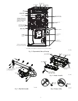
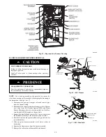
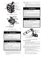
REINSTALL BURNER ASSEMBLY
To reinstall burner assembly:
1. Attach flame sensor to burner assembly.
2. Insert one--piece burner in slot on sides of burner box and
slide burner back in place.
3. Reattach HSI wires to HSI.
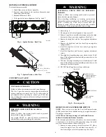
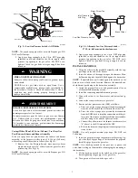
4. Verify igniter to burner alignment. See Fig. 6 and 7.
2-1/2-in.
(64.4)
1-1/4-in.
(31.8)
A11405
Fig. 6 -- Igniter Position -- Back View
2 − in.
(2.5 mm
3/8 − in.
3/16− in.
, +0.8 -1.5)
(50 mm)
(9.6 mm)
(4.6 mm)
3/32 − in., +1/32 -3/64-in.
A12392
Fig. 7 -- Igniter Position -- Side View
CONVERT GAS VALVE
UNIT DAMAGE HAZARD
Failure to follow this caution may result in unit damage
The G or J gas valve must be converted and pre--adjusted
before operating on natural gas. The E valves must be
pre--adjusted before operating on natural gas. If left this
way, sooting and corrosion will occur leading to early heat
exchanger failure.
CAUTION
!
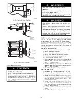
FIRE, EXPLOSION, ELECTRICAL SHOCK
HAZARD
Failure to follow this warning could result in personal
injury, death or property damage.
Gas supply MUST be shut off before disconnecting
electrical power and proceeding with conversion.
!
WARNING
ELECTRICAL SHOCK, FIRE OR EXPLOSION
HAZARD
Failure to follow this warning could result in personal
injury, death or property damage.
Before installing, modifying, or servicing system, main
electrical disconnect switch must be in the OFF position and
install a lockout tag. There may be more than one
disconnect switch. Lock out and tag switch with a suitable
warning label. Verify proper operation after servicing.
!
WARNING
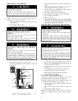
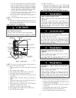
1. Refer to Fig. 8.
2. Be sure gas and electrical supplies to furnace are off.
3. Remove caps that conceal the adjustment screws for high
heat and low heat gas--valve regulators. (See Fig. 8.)
4. Remove the high heat and low heat regulator adjustment
screws.
5. Remove the high heat and low heat Propane regulator
springs (white).
6. Install the high heat and low heat natural gas regulator
springs (silver).
7. Install the high heat and low heat regulator adjustment
screws.
8. Turn high heat stage adjusting screw clockwise (in) 12 full
turns. This will increase the manifold pressure closer to the
natural set point.
9. Turn low heat stage adjusting screw clockwise (in) 9.5 full
turns. This will increase the manifold pressure closer to the
natural gas low heat set point.
10. DO NOT install regulator seal caps at this time.
ON/OFF Switch
Regulator Seal Cap
Regulator Adjustment
Regulator Seal Cap
under Cap
1/2” NPT Outlet
1/8” NPT Manifold
Pressure Tap
1/8” NPT Inlet
Pressure Tap
1/2” NPT Inlet
TWO-STAGE
A11152
Fig. 8 -- Two--stage valve
REMOVE LOW GAS PRESSURE SWITCH
NOTE
: There are two ways that the Low Gas Pressure Switch
(LGPS) could have been installed during the original natural to
Propane gas conversion.
All 14 3/16-in. (360 mm) Casings or Vent Passed Between
Inducer Assembly and Burner Assembly
If the vent pipe passes between the inducer and burner assembly,
or the furnace is a 14 3/16-in. (360 mm) wide casing, the switch
may have been installed as follows (See Fig 9).
1. Remove low--gas pressure switch, brass street 90
_
elbow,
brass Hex nipple, brass Tee and black iron street 90
_
el-
bow from the gas valve inlet pressure tap. (See Fig 9.)


