


2
ELECTRICAL SHOCK, FIRE OR EXPLOSION
HAZARD
Failure to follow this warning could result in personal
injury, death or property damage.
Before installing, modifying, or servicing system, main
electrical disconnect switch must be in the OFF position and
install a lockout tag. There may be more than one
disconnect switch. Lock out and tag switch with a suitable
warning label. Verify proper operation after servicing.
!
WARNING
This instruction covers the installation of gas conversion kit Part
No. KGAPN43012SP to convert the following furnaces from
Propane gas usage to natural gas usage. See appropriate section
for your furnace type.
Section 1
—59TP5, 925T, PG95X_T 4--Way Multipoise, Hot
Surface Ignition, 2--Stage Condensing Furnaces. This kit is
designed for use in furnaces with 40,000 through 120,000 Btuh
gas input rates.
Section 2
—58CTA, 58CTX, 312AAV, 312JAV, 33.3--in. (846
mm) High, Induced--Combustion, Hot--Surface Ignition, 2-Stage
Non-Condensing Furnaces. This kit is designed for use in
furnaces with 42,000 through 154,000 Btuh gas input rates.
DESCRIPTION AND USAGE
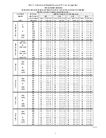
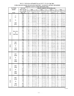
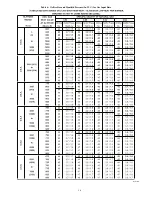
See Table 1 for kit contents. This kit is designed for use in the
furnaces listed in Table 2 and 4. To accommodate many different
furnace models, more parts are shipped in kit than will be needed
to complete conversion. When installation is complete, discard
extra parts.
Table 1 – KGAPN43012SP Contents
COMPONENT
NUMBER
QTY
DESCRIPTION
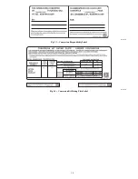
319965---449
1
LABEL,SHIPPING
323267---701
1
PARTS ASSY #42
323267---702
1
PARTS ASSY #43
323267---703
1
PARTS ASSY #44
323267---704
1
PARTS ASSY #45
338304---701
1
LABEL KIT
338304---702
1
LABEL KIT
AG---KGAPN2SP---XX
1
INSTRUCTIONS
EF39ZW037
2
VALVE CVRSN KIT
CA64AS001
1
PLUG, PIPE
SECTION 1
Table 2 – 35--in High Efficiency 2--Stage Condensing
Furnaces
MODEL NUMBERS BEGINNING WITH:
59TP5
925T
PG95X_T
INSTALLATION
1. Set room thermostat to lowest setting or “OFF”.
2. Remove outer doors.
3. Disconnect power at external disconnect, fuse or circuit
breaker.
4. Turn off gas at external shut-off or gas meter.
5. Remove outer doors and set aside.
6. Turn electric switch on gas valve to OFF.
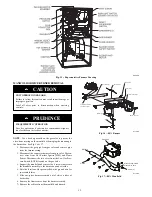
MANIFOLD/ORIFICE/BURNER REMOVAL
UNIT OPERATION HAZARD
Failure to follow this caution may result in unit damage or
improper operation.
Label all wires prior to disconnection when servicing
controls.
CAUTION
!
D’EQUIPEMENT D’OPERATION
Toute erreur de câblage peut être une source de danger et de
panne.
Lors des opérations d’entretien des commandes, étiqueter
tous les fils avant de les déconnecter.
PRUDENCE
!
NOTE
: Use a back-up wrench on the gas valve to prevent the
valve from rotating on the manifold or damaging the mounting to
the burner box.
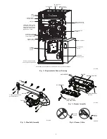
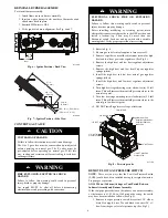
1. Disconnect the gas pipe from gas valve and remove pipe
from the furnace casing. See Fig. 1.
2. Disconnect the connector harness from gas valve Discon-
nect wires from Hot Surface Igniter (HSI) and Flame
Sensor. Disconnect the two wires from the Low Gas Pres-
sure Switch (LGPS) located on the gas valve.
3. Support the manifold and remove the 4 screws that secure
the manifold assembly to the burner box and set aside.
4. Note the location of the green/yellow wire ground wire for
re-assembly later. See Fig. 2.
5. Slide one--piece burner assembly out of slots on sides of
burner box.
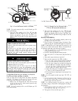
6. Remove the flame sensor from the burner assembly. See
Fig. 3.
7. Remove the orifices from the manifold and discard.
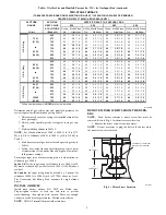
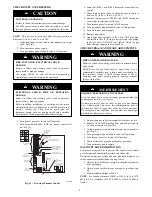
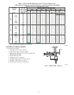
ORIFICE SELECTION/DERATE
UNIT DAMAGE HAZARD
Failure to follow this caution may result in unit damage.
DO NOT re--drill burner orifices. Improper drilling may
result in burrs, out--of--round holes, etc. Obtain new orifices
if orifice size must be changed. (See Fig. 4.)
CAUTION
!


