


13
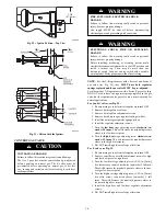
NOx DEVICE INSTALLATION (when required)
The following models must have NOx baffles installed (58CTX
and 312JAV). NOx baffles are not included in this kit and must
be ordered separately or reused if retained from original
conversion to Propane.
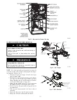
For NOx device installation, follow these additional steps:
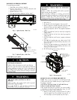
1. Remove the screw underneath the heat exchanger inlet that
secures the NOx device in the heat exchanger. (See Fig.
18.)
2. Use a pair of needle nose pliers to install the NOx device.
3. Squeeze the sides of the device, if necessary, to install in
the heat exchanger.
4. Re-install screw in hole underneath heat exchanger inlet.
NOTE
: It is very IMPORTANT to reinstall the NOx bracket
mounting screw.
5. Repeat steps for each heat exchanger.
A02195
Fig. 18 -- NOx Device
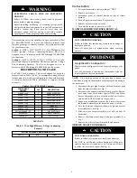
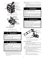
ORIFICE SELECTION/DERATE
UNIT DAMAGE HAZARD
Failure to follow this caution may result in unit damage.
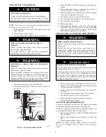
DO NOT re--drill burner orifices. Improper drilling may
result in burrs, out--of--round holes, etc. Obtain new orifices
if orifice size must be changed. (See Fig. 19.)
CAUTION
!
BURNER
ORIFICE
BURNER
ORIFICE
A96249
Fig. 19 -- Burner Orifice
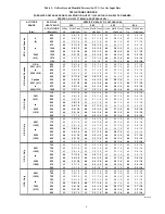
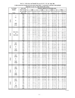
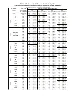
Determine natural gas orifice size and manifold pressures for
correct input at installed altitude by using Table 5 or 6.
NOTE
: All models in all positions except Low NOx models in
downflow and horizontal positions use Table 5 (22,000 Btuh per
burner). Low NOx models in downflow or horizontal positions
must use Table 6 (21,000 Btuh per burner). See input listed on
rating plate.
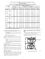
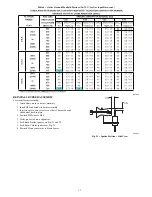
1. Obtain yearly heat--value average (at installed altitude) for
local gas supply.
2. Obtain yearly specific--gravity average for local gas sup-
ply.
3. Find installation altitude in Table 5 or 6.
NOTE
: For Canada altitudes of 2000 to 4500 ft., use U.S.A.
Altitudes of 2001 to 3000 ft. in Table 5 or 6.
4. Find closest natural gas heat value and specific gravity in
Table 5 or 6.
5. Follow heat--value line and specific--gravity line to point
of intersection to find orifice size and high and low--heat
manifold pressure settings.
Furnace gas input rate on furnace rating plate is for installations at
altitudes up to 2000 ft. (610 M).
In the U.S.A
.; the input rating for altitudes above 2000 ft. (610
M) must be reduced by 4 percent for each 1000 ft. (305 M) above
sea level.
In Canada
, the input rating must be derated by 5 percent for
altitudes of 2000 ft. to 4500 ft. (610 M to 1372 M) above sea
level.
The Conversion Kit Rating Plate accounts for high altitude
derate.
INSTALL ORIFICES
1. Install main burner orifices. DO NOT use Teflon tape. Fin-
ger-tighten orifices at least one full turn to prevent
cross-threading, then tighten with wrench.
2. There are enough orifices in each kit for largest furnace.
Discard extra orifices.
NOTE
: DO NOT reinstall the manifold at this time.
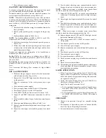
REMOVE MIXER SCREWS
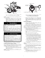
NOTE
:
Each burner contains a mixer screw that must be
removed. Refer to Fig. 20 for the mixer screw location.
1. Remove the mixer screws from the burners.
NOTE
: It is not necessary to plug the hole in the burner when
the mixer screws are removed.
1.9”
(48.76 mm)
1.8”
(46.96 mm)
Location of mixer screw
that must be removed
A11501
Fig. 20 -- Mixer Screw Location


