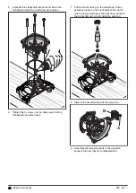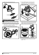
5. Remove the protective plates (K and L).
K
L
7.14.3 To disassemble the bevel gear
Note: The illustrations in this section shows one of the
models, but the procedure is the same for the 2 models.
To remove the gearbox on page 52
To remove the gearbox on page 53.
2. Use pliers to remove the snap rings (O and P).
O
P
3. Put on protective gloves. Use a hot air gun to
increase the temperature of the angle gear to
approximately 110°C - 140°C. Hit the gearbox
against a wooden block.
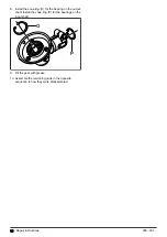
4. Remove the input shaft assembly (Q) from the gear
housing. Remove the snap ring (S) from the input
shaft (V). Remove the bearings (T and U).
U
V
Q
T
S
R
5. Increase the temperature of the gear housing to
approx. 140°C.
54 - Repair instructions
935 - 001 -
Summary of Contents for 531RB
Page 1: ...Workshop manual 541RB 531RB English 935 001 ...
Page 10: ...5 Servicing tools 10 8 3 11 12 9 1 2 4 5 6 7 13 14 15 16 10 Servicing tools 935 001 ...
Page 61: ...935 001 Technical data 61 ...
Page 62: ...62 Technical data 935 001 ...
Page 63: ...935 001 Technical data 63 ...
Page 64: ...114 10 74 26 2019 04 18 ...


