


Page 12 of 24
Hunting Energy Services (Well Intervention) Ltd
4.5 Equipment Tests
Prior to testing
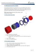
disassemble the X-over and clean with a suitable cleaner, then re-assemble with new
O-rings. Ensure that the equipment is placed in a designated safe test area
ONLY.
NOTE:
ANY
leakage of test fluid detected while the equipment is pressurised is cause for rejection.
Determine the cause of the leak, repair it and re-test.
NEVER
attempt to loosen or tighten a connection while pressurised.
NEVER
attempt to connect the X-over to equipment incorporating connections other than the
specific quick union/test port. Failure to do so will result in damage to the equipment seal
areas and/or threads.
To prevent personal injury, keep fingers/other extremities AWAY from Acme threads whilst
making up the quick union collar
.
4.5.1 Annual Maintenance: Function test to Max. Working Pressure (MWP)
This body test checks that the equipment can withstand the Maximum Working Pressure. To test, take
the following steps:
No leaks can be accepted
1.
Cap off the bottom with an approved blanking cap. Fill with test fluid and cap off the top with
an approved blanking plug.
2.
Bleed off all trapped air.
3.
Connect a test pump to a suitable test port.
4.
CLEAR
the area of all personnel before proceeding
5.
Apply maximum working pressure to the X-Over and hold for five minutes. Reduce pressure
to 0-PSI. Re-Pressurise to MWP and hold for fifteen minutes. Reduce pressure to 0-PSI. Re-
pressurise to (300PSI) and hold for five minutes. Reduce pressure to 0-PSI.
6.
Disconnect and remove the blanking plug and cap.
4.5.2 5 Year major Survey: Hydrostatic pressure test to Test Pressure (TP)
This body test checks that the equipment can withstand the Design Pressure. To test, take the
following steps.
No leaks can be accepted
1.
Cap off the bottom with an approved blanking cap. Fill with test fluid and then cap the top
with an approved blanking plug.
2.
Bleed off all trapped air.
3.
Connect a test pump to a suitable test port
4.
CLEAR
the area of all personnel before proceeding.
5.
Apply maximum test pressure to the X-Over, hold for five minutes and reduce pressure to 0-
PSI. Re-Pressurise to TP, hold for fifteen minutes and reduce pressure to 0-PSI. Re-pressurise
to (300PSI), hold for five minutes and reduce pressure to 0-PSI.
6.
Disconnect and remove the blanking plug and cap.
Summary of Contents for X-Over
Page 1: ...X Over Tool Manual Manual Revision Prepared Checked Approved Date C P Kinnaird 09 06 2017 ...
Page 15: ...Page 15 of 24 Hunting Energy Services Well Intervention Ltd Annex I Quick Union Table ...
Page 16: ...Page 16 of 24 Hunting Energy Services Well Intervention Ltd ...
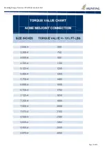
Page 17: ...Page 17 of 24 Hunting Energy Services Well Intervention Ltd Annex II Torque Value Chart ...
Page 18: ...Huntin ng Energy Se ervices Well l Intervention n Ltd Page 18 o of 24 ...
Page 19: ...Page 19 of 24 Hunting Energy Services Well Intervention Ltd Annex III API Flanges ...
Page 20: ...Page 20 of 24 Hunting Energy Services Well Intervention Ltd ...