background image

INSTALLATION

18


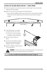
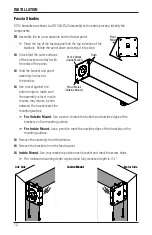
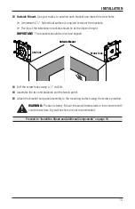
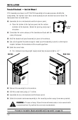
Attach the fascia panel.


Place the top of the fascia panel into the top indention of the 
brackets. Rotate the panel down and snap it into place. 

For Blockout Shades proceed below. For all other shades, proceed to “Connect the Power” 

on page 22.

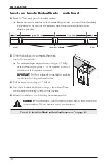
Assemble the Side Channels — Cassette Blockout Shades Only


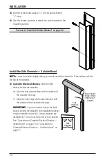
Remove the adhesive from the back of the light blocker.


Thread wool pile from channel into the light blocker channel.


Slide the light blocker into the top of the side channel.


Press the light blocker into place to secure the adhesive. 

For inside mount shades, proceed to “Install the Side Channels — Inside Mount” on page 19. 

For outside mount shades, proceed to “Install the Side Channels — Outside Mount” on page 20.

Fascia

Panel

Peel 

Adhesive

Back

Wool

Pile

Light

Blocker

Installed

Front

Summary of Contents for Alustra Woven Textures LT525

Page 1: ...Installation Operation Care Alustra Woven Textures Roller Shades Designer Roller and Screen Shades ST30 ST50 and LT525 Cassette Cassette Blockout Fascia Fascia Blockout...

Page 2: ...ing interference that may cause undesired operation This equipment has been tested and found to comply with the limits for a Class B digital device pursuant to Part 15 of the FCC Rules These limits ar...

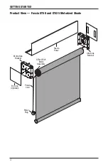
Page 3: ...GETTING STARTED 1 Product View Cassette Motorized Shade ST30 Motor Assembly Antenna Wire Cassette Bracket Cassette Power Cord Power Plug Power Supply Power Plug ST50 LT525 Motor Assembly Power Cord...

Page 4: ...tallation Brackets Antenna Wire Cassette Bottom Channel Bottom Plug Outside Mount Only Hole Plug Outside Mount Only Side Channel Flat Metal Bottom Bar Light Blocker Wool Pile Power Plug ST50 LT525 Mot...

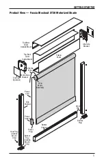
Page 5: ...GETTING STARTED 3 Product View Fascia ST30 Motorized Shade Idle Side Bracket ST30 Motor Assembly Antenna Wire End Cap Optional Fascia Panel Motor Side Bracket Power Cord Power Plug Power Supply...

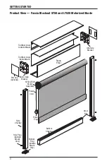
Page 6: ...4 GETTING STARTED Product View Fascia ST50 and LT525 Motorized Shade Power Plug ST50 LT525 Motor Assembly Power Cord Idle Side Bracket Motor Side Bracket End Cap Optional Fascia Panel...

Page 7: ...Cap Optional Fascia Panel Idle Side Bracket Motor Side Bracket Top Rear Cover Outside Mount Top Rear Cover Inside Mount Power Cord ST30 Motor Assembly Power Plug Power Supply Bottom Channel Side Chann...

Page 8: ...de Bracket End Cap Optional Motor Side Bracket Power Cord Bottom Channel Side Channel Flat Metal Bottom Bar Wool Pile Power Plug ST50 LT525 Motor Assembly Fascia Panel Top Rear Cover Outside Mount Top...

Page 9: ...l is recommended Paperclip Cassette Shades Power drill 3 32 drill bit and 1 4 hex driver Fascia Shades Power drill 1 8 drill bit and 5 32 hex driver In addition you will need fasteners designed to wor...

Page 10: ...he table Fascia and Fascia Blockout Shades Brackets are different for ST30 and ST50 LT525 Refer to the illustrations below to identify the correct one for your order An idle and motor bracket are incl...

Page 11: ...r to the appropriate page below based on your order Inside Mount for Cassette and Cassette Blockout Shades page 10 Outside Mount for Cassette and Cassette Blockout Shades page 11 Fascia Shades page 12...

Page 12: ...s 4 for the cassette to be flush with the front of the window casement IMPORTANT The front edges of the installation brackets must be level and aligned to each other Drill the screw holes using a 3 32...

Page 13: ...er the brackets on your marks then mark each of the screw holes A minimum 4 flat vertical surface is required to mount the brackets Drill the screw holes using a 3 32 drill bit Use a level to check th...

Page 14: ...ottom edge to make sure the assembly is level Inside mounts may require a shim between the brackets and the mounting surface For Outside Mount Use a pencil to mark the bottom and outside edges of the...

Page 15: ...brackets should be level and aligned Drill the screw holes using a 1 8 drill bit Assemble the two end brackets and the fascia panel Attach the bracket and panel assembly to the mounting surface using...

Page 16: ...and panel assembly in place at the window Use a level against the bottom edge to make sure the assembly is level A shim may be required between the brackets and the mounting surface Mark the screw hol...

Page 17: ...e the assembly is level A shim is required between the brackets and the mounting surface Mark the screw holes A minimum 41 8 flat vertical surface is required to mount the brackets The top of the inst...

Page 18: ...Hold the shade with the motor Reset and Manual Operation switches facing the floor and the power cord close to the wall CAUTION Do not cut the antenna wire or wrap it around the power cord Install th...

Page 19: ...et compressing the spring As you rotate the shade up and into position align the motor with the motor mount and push in When you set the shade in place route the power cord Use a pair of pliers to ins...

Page 20: ...ckout Shades Only Remove the adhesive from the back of the light blocker Thread wool pile from channel into the light blocker channel Slide the light blocker into the top of the side channel Press the...

Page 21: ...s The back of the side channel is flush with the bracket Ensure there isn t a gap between the side channel and the sill The side channel should sit on the sill Also ensure the back of the side channel...

Page 22: ...ht blocker behind the cassette Abut the side channel flush with the bottom of the cassette end cap Align the outer edge of the side channels with the outside of the cassette end caps IMPORTANT If you...

Page 23: ...a level Mark the mounting holes for the side channel to determine where to drill the holes Measure the side to side distance between them The distance between the top two holes and between the bottom...

Page 24: ...plugs pushing them in until they are firmly seated Push the bottom plug into the bottom of the side channels Connect the Power After you have hung the shade in its proper location connect the shade t...

Page 25: ...system a 16 gauge wire is sufficient for the 110V AC input This wire is not provided with your shade order Two shade power supplies DR 120 24 use a switch to select between 100 120V AC or 200 240V AC...

Page 26: ...he current channel light on the multi channel hand held remote control flashes when you press any of the three buttons above the channel lights To change the channel group of shades being addressed by...

Page 27: ...l If there is no response repeat the previous two steps for the remaining channels If the shade does not respond to any channel proceed to Programming Programming CAUTION If your shade s are operating...

Page 28: ...ttons when the shade starts to move Press the STOP MY button when the shade reaches the desired down limit Press the UP or DOWN buttons to fine tune the lower limit position Press the STOP MY and the...

Page 29: ...s necessary proceed as follows Only one shade should have power IMPORTANT If more than one unit is plugged in each one will be changed To Add a Channel Press the PROGRAM button on the back of the hand...

Page 30: ...winds on the roll IMPORTANT Level mounting is essential for proper operation If the fabric winds unevenly and begins to telescope to one side check to ensure the shade is level If the shade is not le...

Page 31: ...he wall switch to position the shade in the desired lowered position Press the yellow button on the motor to set it to the raised position Test the operation of the shade and adjust the upper and lowe...

Page 32: ...rn it to factory settings after 12 seconds This button can also be used to delete all transmitter channels by holding the button down until the shade jogs 3 times The yellow button allows for manual o...

Page 33: ...20 meters or 65 feet In multi channel installations Be sure that the remote control is addressing the channel to which the shade was set If there is more than one motorized shade installed and only o...

Page 34: ...connect the power cord to the shade While holding the top of the shade insert a flat blade screwdriver into the idle installation channel between the spring idle and the bracket With the screwdriver p...

Page 35: ...needed in most circumstances Vacuuming Use a hand held vacuum with low suction for more thorough dust removal Compressed Air Hair Dryer Cool Setting Use compressed air or a hair dryer on a cool settin...

Page 36: ...ed for 5 years from the date of purchase 1 Contact your original dealer place of purchase for warranty assistance 2 Visit hunterdouglas com for additional warranty information frequently asked questio...

Reviews: