Fuel Systems
The fuel systems aboard your Hunter boat consists of the
following components or sub-systems.
Fuel Tank
Fuel Fill
Fuel Vent
Fuel
Lines
Fuel Filters
LPG (Liquefied Petroleum Gas) System
5.1 Fuel Tanks
Your boat is equipped with a fuel tank. In the aft state-
room under the bunk.
The tank is filled through a fuel fill.
If your boat has a metal or aluminum tank installed, then
the fuel tank should be inspected for signs of leaks, cor-
rosion, and/or pitting at least once a year. Corrosion
normally appears as a white, chalky, or flaky substance
on the surface of the tank. Sometimes, it also appears
as pitting or small pockets of missing aluminum. Another
indication of corrosion is bubbles on the paint that coats
the tank. If any of these conditions are present, have an
authorized service technician inspect the tank immedi-
ately. If a leak is found, turn off battery switches and dis-
connect shore power (See Connecting & Disconnecting
Shore Power, AC Electrical System), which explains
the proper way to disconnect and disable any possible
source of ignition). Contact your dealer or Customer
Service immediately.
5.1.1 Fuel Tank Capacity Monitoring
The fuel tank is equipped with a fuel level sending unit, which
provides an electrical signal to the display located at the helm.
•
•
•
•
•
•
•
5.1.1 Fuel Tank Grounding System
The fuel tank and fuel fill on your boat are electrically
grounded to the engine negative. (see the DC Electrical
chapter). This grounding system is designed to prevent
the discharge of static electricity when fueling your boat.
An authorized service technician should inspect this sys-
tem at least once each year.
5.1.2 Fuel Gauge
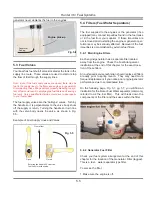
The fuel gauge as shown in Fig. 5.1 is located at the
helm, and is the indicator of the fuel level in your tank.
Visually inspect the reading against what is show-
ing in the tank to see that the gauge is operational.
DANGER
!
!
Never enter the engine room without proper ventila-
tion first. A spark caused by power tools or lighting
equipment could result in fire or explosion which
could cause personal injury or death.
Fig. 5.1
g
ated at
ated at
Hunter 36 • Fuel Systems
5.3
Summary of Contents for H36
Page 1: ...Operator s Operator s Manual Manual H36 H36 V1 040107 P N 1031378 ...
Page 2: ......
Page 9: ...Introduction Introduction H36 H36 Chapter 1 Chapter 1 V1 040107 P N 1031378 ...
Page 14: ...Hunter 36 Introduction 1 6 Notes ...
Page 15: ...V1 040107 P N 1031378 and Documents Documents Forms Forms H36 H36 Chapter 2 Chapter 2 ...
Page 26: ...Hunter 36 Documents and Forms Maintenance Log Date Maintenance Performed Hourmeter 2 12 ...
Page 27: ...Hunter 36 Documents and Forms 2 13 Date Maintenance Performed Hourmeter Maintenance Log ...
Page 33: ...Hunter 36 Documents and Forms 2 19 Spare Parts List ...
Page 34: ...Hunter 36 Documents and Forms Dates of practice drills and onboard safety inspections 2 20 ...
Page 35: ...Hunter 36 Documents and Forms 2 21 My personal preferences for maintenance items safety gear ...
Page 36: ...Hunter 36 Documents and Forms Notes 2 22 ...
Page 37: ...DC 071609 Limited Limited Warranty Warranty Chapter 3 Chapter 3 ...
Page 38: ...This Page Intentionally Left Blank Hunter Limited Warranty 3 2 ...
Page 47: ...Boating Boating Safety Safety H36 H36 Chapter 4 Chapter 4 V1 040107 P N 1031378 ...
Page 68: ...Hunter 36 Boating Safety 4 22 Notes ...
Page 69: ...Chapter 5 Chapter 5 Fuel Fuel Systems Systems H36 H36 V1 040107 P N 1031378 ...
Page 75: ...Fig 5 7 A Quick Fuel Filter Reference Hunter 36 Fuel Systems 5 7 ...
Page 82: ...Notes Hunter 36 Fuel Systems 5 14 ...
Page 83: ...Underwater Underwater Gear Gear H36 H36 Chapter 6 Chapter 6 V1 040107 P N 1031378 ...
Page 92: ...Hunter 36 Underwater Gear 6 10 Notes ...
Page 93: ...DC Electric DC Electric Systems Systems H36 H36 Chapter 7 Chapter 7 V1 040107 P N 1031378 ...
Page 103: ...Hunter 36 DC Electric 7 11 7 8 BASIC DC POWER SUPPLY SYSTEM DIAGRAM ...
Page 104: ...Hunter 36 DC Electric 7 12 Notes ...
Page 106: ...Hunter 36 DC Electric 7 14 Notes ...
Page 108: ...Hunter 36 DC Electric 7 16 Notes ...
Page 109: ...AC Electric AC Electric Systems Systems H36 H36 Chapter 8 Chapter 8 V1 040107 P N 1031378 ...
Page 118: ...This Page Intentionally Left Blank Hunter 36 AC Electric Systems 8 10 ...
Page 119: ...Hunter 36 AC Electric Systems 8 11 7 8 AC DC Electric Power Supply Diagram pp y g ...
Page 120: ...Hunter 36 AC Electric Systems 8 12 This Page Intentionally Left Blank ...
Page 121: ...Hunter 36 AC Electric Systems 8 13 Notes ...
Page 122: ...Hunter 36 AC Electric Systems 8 14 Notes ...
Page 123: ...Water Water Systems Systems H36 H36 Chapter 9 Chapter 9 V1 040107 P N 1031378 ...
Page 130: ...Hunter 36 Water Systems 9 8 This Page Intentionally Left Blank ...
Page 132: ...Hunter 36 Water Systems 9 10 This Page Intentionally Left Blank ...
Page 133: ...Hunter 36 Water Systems 9 11 Notes ...
Page 134: ...Hunter 36 Water Systems 9 12 Notes ...
Page 135: ...Waste Waste Systems Systems H36 H36 Chapter 10 Chapter 10 V1 040107 P N 1031378 ...
Page 144: ...This Page Intentionally Left Blank Hunter 36 Waste and Sanitation Systems 10 10 ...
Page 146: ...This Page Intentionally Left Blank Hunter 36 Waste and Sanitation Systems 10 12 ...
Page 148: ...This Page Intentionally Left Blank Hunter 36 Waste and Sanitation Systems 10 14 ...
Page 149: ...Sump Pump Layout Grey Water p p y y Hunter 36 Waste and Sanitation Systems 10 15 ...
Page 150: ...This Page Intentionally Left Blank Hunter 36 Waste and Sanitation Systems 10 16 ...
Page 152: ...This Page Intentionally Left Blank Hunter 36 Waste and Sanitation Systems 10 18 ...
Page 153: ...Hunter 36 Waste and Sanitation Systems 10 19 Notes ...
Page 154: ...Hunter 36 Waste and Sanitation Systems 10 20 Notes ...
Page 164: ...Hunter 36 Engines and Transmissions 11 10 This Page Intentional Left Blank ...
Page 165: ...V1 040107 P N 1031378 Sails Sails Rigging H36 H36 Chapter 12 Chapter 12 and and ...
Page 171: ...Hunter 36 Sails and Rigging 12 7 Standing Rigging Details Standard ...
Page 172: ...Hunter 36 Sails and Rigging 12 8 Standing Rigging Details Furling ...
Page 173: ...Hunter 36 Sails and Rigging 12 9 Mast Upper Spreader Tip Details pp p p H A B C D E F G ...
Page 174: ...Hunter 36 Sails and Rigging 12 10 C A B D E F G H J K I Mast Lower Spreader Tip Details p p ...
Page 175: ...Hunter 36 Sails and Rigging 12 11 Standing Rigging Details ...
Page 179: ...Hunter 36 Sails and Rigging 12 15 Typical Boom Reefing Layout yp g y ...
Page 180: ...Hunter 36 Sails and Rigging 12 16 Rope Vang Details Standard Vang Details ...
Page 181: ...Hunter 36 Sails and Rigging 12 17 Rigid Vang Details Optional Vang Details ...
Page 184: ...Hunter 36 Sails and Rigging 12 20 JIB LINE TIES OFF ON CLEAT Jib Furling Line Layout ...
Page 185: ...Hunter 36 Sails and Rigging 12 21 Bridle Configuration ...
Page 186: ...Hunter 36 Sails and Rigging 12 22 Optional Mainsheet Traveler Layout ...
Page 190: ...Hunter 36 Sails and Rigging 12 26 Optional Spinnaker Layout ...
Page 191: ...Hunter 36 Sails and Rigging 12 27 Notes ...
Page 192: ...Hunter 36 Sails and Rigging 12 28 Notes ...
Page 193: ...Getting Getting Underway Underway H36 H36 Chapter 13 Chapter 13 V1 030107 P N 1031378 ...
Page 200: ...Hunter 36 Getting Underway 13 8 Notes ...
Page 201: ...Maintenance H36 H36 Chapter 14 Chapter 14 V1 040107 P N 1031378 ...
Page 214: ...Notes Hunter 36 Maintenance 14 14 ...
Page 215: ...Exterior Lifting Points g Hunter 36 Maintenance 14 15 ...
Page 216: ...Hunter 36 Maintenance 14 16 This Page Intentionally Left Blank ...
Page 217: ...Hunter 36 Maintenance 14 17 Exterior Lifting Points Saildrive g ...
Page 218: ...Hunter 36 Maintenance 14 18 This Page Intentionally Left Blank ...
Page 219: ...Glossary Glossary H36 H36 Chapter 15 Chapter 15 V1 040107 P N 1031378 ...

