Hunter 36 • Boating Safety
4.4
Anchor and line *
Boat hook
Bucket & Sponge
Commonly used spare parts
Distress signal kit*
Docking lines
Engine and accessory manuals*
Extra keys
Extra V-belts
Fenders
First aid kit
Flashlight & extra batteries
Manually operated bilge pump
Navigational charts
Owner’s Manual
Replacement bulbs
VHF radio
Spare fuel and oil filters
Tool kit
*Provided in Loose Gear Kit (US Boats only)
4.1.7 Personal Flotation Devices (PFDs)
There must be one United States Coast Guard approved
wearable personal flotation device of Type I, II, or III for
each person on board your boat. The PFDs must be in
serviceable condition and readily accessible. A minimum
of three PFDs (two wearable and one throwable) is
required regardless of the number of persons on board.
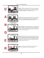
(A) PFD Type I, Wearable:
This offshore life jacket has the greatest buoyancy. It is
effective for all waters where rescue may be delayed. Its
design allows for turning most unconscious persons in
the water from face down position to a vertical or face-up
position.
(B) PFD Type II, Wearable:
This near-shore buoyant vest provides less buoyancy
than a Type I PFD. It is intended for calm inland waters
or waters where there is a chance of quick rescue. It turns
its wearer to a face-up position as does the Type I PFD,
but the turning action is not as pronounced as the Type
I, and it will not turn as many persons under the same
conditions as a Type I.
(C) PFD Type III, Wearable:
Classified as a flotation aid, this PFD allows wearers
•
•
•
•
•
•
•
•
•
•
•
•
•
•
•
•
•
•
•
to place themselves in a vertical or face-up position in
the water. Type III PFD has the same minimum buoy-
ancy as a Type II PFD. It has little or no turning ability.
People participating in water sports often prefer this PFD
because it is intended for use in waters where quick res-
cue is possible and it is generally the most comfortable
for continuous wear.
(D) PFD Type IV, Throwable:
You must also have aboard at least one throwable PFD
Type IV device. The Type IV device can be thrown to a
person in the water and held by the user until rescued.
The design does not allow it to be worn. The most com-
mon Type IV PFD are buoyant cushions or ring buoys.
This PFD must be immediately available for use and in
serviceable condition.
4.2 Carbon Monoxide Hazard
(See enclosed brochure concerning Carbon Monoxide poison-
ing and preventing)
As all responsible yachtsmen know, there are unseen
dangers when boating. One danger is serious enough
that we feel the need to specifically bring it to your
attention. It is odorless, colorless, and tasteless, but
can be harmful or fatal if inhaled. Its name is CARBON
MONIXIDE (CO)
4.2.1 Carbon Monoxide Safety
This section is intended to provide educational informa-
tion about carbon monoxide relative to boats and boat-
ing. Carbon Monoxide accumulation is affected by boat
geometry, hatch, window, and door openings, ventilation
openings, proximity to other structures and boats, wind
direction, boat speed, boat maintenance, and a multi-
tude of other variables. This section discusses many of
these and enables the boat owner to better understand
all conceivable variables. Therefore, the boat owner is
cautioned not to exclusively rely on it to prevent the accu-
mulation of Carbon Monoxide.
4.2.2 What is Carbon Monoxide?
Carbon Monoxide is a highly poisonous gas formed by the
combination of carbon and oxygen. Commonly referred
to as CO, its chemical formula is C for carbon and O for
oxygen. CO is a colorless, odorless, and tasteless gas
that, by itself, cannot be detected by human senses. CO
Summary of Contents for H36
Page 1: ...Operator s Operator s Manual Manual H36 H36 V1 040107 P N 1031378 ...
Page 2: ......
Page 9: ...Introduction Introduction H36 H36 Chapter 1 Chapter 1 V1 040107 P N 1031378 ...
Page 14: ...Hunter 36 Introduction 1 6 Notes ...
Page 15: ...V1 040107 P N 1031378 and Documents Documents Forms Forms H36 H36 Chapter 2 Chapter 2 ...
Page 26: ...Hunter 36 Documents and Forms Maintenance Log Date Maintenance Performed Hourmeter 2 12 ...
Page 27: ...Hunter 36 Documents and Forms 2 13 Date Maintenance Performed Hourmeter Maintenance Log ...
Page 33: ...Hunter 36 Documents and Forms 2 19 Spare Parts List ...
Page 34: ...Hunter 36 Documents and Forms Dates of practice drills and onboard safety inspections 2 20 ...
Page 35: ...Hunter 36 Documents and Forms 2 21 My personal preferences for maintenance items safety gear ...
Page 36: ...Hunter 36 Documents and Forms Notes 2 22 ...
Page 37: ...DC 071609 Limited Limited Warranty Warranty Chapter 3 Chapter 3 ...
Page 38: ...This Page Intentionally Left Blank Hunter Limited Warranty 3 2 ...
Page 47: ...Boating Boating Safety Safety H36 H36 Chapter 4 Chapter 4 V1 040107 P N 1031378 ...
Page 68: ...Hunter 36 Boating Safety 4 22 Notes ...
Page 69: ...Chapter 5 Chapter 5 Fuel Fuel Systems Systems H36 H36 V1 040107 P N 1031378 ...
Page 75: ...Fig 5 7 A Quick Fuel Filter Reference Hunter 36 Fuel Systems 5 7 ...
Page 82: ...Notes Hunter 36 Fuel Systems 5 14 ...
Page 83: ...Underwater Underwater Gear Gear H36 H36 Chapter 6 Chapter 6 V1 040107 P N 1031378 ...
Page 92: ...Hunter 36 Underwater Gear 6 10 Notes ...
Page 93: ...DC Electric DC Electric Systems Systems H36 H36 Chapter 7 Chapter 7 V1 040107 P N 1031378 ...
Page 103: ...Hunter 36 DC Electric 7 11 7 8 BASIC DC POWER SUPPLY SYSTEM DIAGRAM ...
Page 104: ...Hunter 36 DC Electric 7 12 Notes ...
Page 106: ...Hunter 36 DC Electric 7 14 Notes ...
Page 108: ...Hunter 36 DC Electric 7 16 Notes ...
Page 109: ...AC Electric AC Electric Systems Systems H36 H36 Chapter 8 Chapter 8 V1 040107 P N 1031378 ...
Page 118: ...This Page Intentionally Left Blank Hunter 36 AC Electric Systems 8 10 ...
Page 119: ...Hunter 36 AC Electric Systems 8 11 7 8 AC DC Electric Power Supply Diagram pp y g ...
Page 120: ...Hunter 36 AC Electric Systems 8 12 This Page Intentionally Left Blank ...
Page 121: ...Hunter 36 AC Electric Systems 8 13 Notes ...
Page 122: ...Hunter 36 AC Electric Systems 8 14 Notes ...
Page 123: ...Water Water Systems Systems H36 H36 Chapter 9 Chapter 9 V1 040107 P N 1031378 ...
Page 130: ...Hunter 36 Water Systems 9 8 This Page Intentionally Left Blank ...
Page 132: ...Hunter 36 Water Systems 9 10 This Page Intentionally Left Blank ...
Page 133: ...Hunter 36 Water Systems 9 11 Notes ...
Page 134: ...Hunter 36 Water Systems 9 12 Notes ...
Page 135: ...Waste Waste Systems Systems H36 H36 Chapter 10 Chapter 10 V1 040107 P N 1031378 ...
Page 144: ...This Page Intentionally Left Blank Hunter 36 Waste and Sanitation Systems 10 10 ...
Page 146: ...This Page Intentionally Left Blank Hunter 36 Waste and Sanitation Systems 10 12 ...
Page 148: ...This Page Intentionally Left Blank Hunter 36 Waste and Sanitation Systems 10 14 ...
Page 149: ...Sump Pump Layout Grey Water p p y y Hunter 36 Waste and Sanitation Systems 10 15 ...
Page 150: ...This Page Intentionally Left Blank Hunter 36 Waste and Sanitation Systems 10 16 ...
Page 152: ...This Page Intentionally Left Blank Hunter 36 Waste and Sanitation Systems 10 18 ...
Page 153: ...Hunter 36 Waste and Sanitation Systems 10 19 Notes ...
Page 154: ...Hunter 36 Waste and Sanitation Systems 10 20 Notes ...
Page 164: ...Hunter 36 Engines and Transmissions 11 10 This Page Intentional Left Blank ...
Page 165: ...V1 040107 P N 1031378 Sails Sails Rigging H36 H36 Chapter 12 Chapter 12 and and ...
Page 171: ...Hunter 36 Sails and Rigging 12 7 Standing Rigging Details Standard ...
Page 172: ...Hunter 36 Sails and Rigging 12 8 Standing Rigging Details Furling ...
Page 173: ...Hunter 36 Sails and Rigging 12 9 Mast Upper Spreader Tip Details pp p p H A B C D E F G ...
Page 174: ...Hunter 36 Sails and Rigging 12 10 C A B D E F G H J K I Mast Lower Spreader Tip Details p p ...
Page 175: ...Hunter 36 Sails and Rigging 12 11 Standing Rigging Details ...
Page 179: ...Hunter 36 Sails and Rigging 12 15 Typical Boom Reefing Layout yp g y ...
Page 180: ...Hunter 36 Sails and Rigging 12 16 Rope Vang Details Standard Vang Details ...
Page 181: ...Hunter 36 Sails and Rigging 12 17 Rigid Vang Details Optional Vang Details ...
Page 184: ...Hunter 36 Sails and Rigging 12 20 JIB LINE TIES OFF ON CLEAT Jib Furling Line Layout ...
Page 185: ...Hunter 36 Sails and Rigging 12 21 Bridle Configuration ...
Page 186: ...Hunter 36 Sails and Rigging 12 22 Optional Mainsheet Traveler Layout ...
Page 190: ...Hunter 36 Sails and Rigging 12 26 Optional Spinnaker Layout ...
Page 191: ...Hunter 36 Sails and Rigging 12 27 Notes ...
Page 192: ...Hunter 36 Sails and Rigging 12 28 Notes ...
Page 193: ...Getting Getting Underway Underway H36 H36 Chapter 13 Chapter 13 V1 030107 P N 1031378 ...
Page 200: ...Hunter 36 Getting Underway 13 8 Notes ...
Page 201: ...Maintenance H36 H36 Chapter 14 Chapter 14 V1 040107 P N 1031378 ...
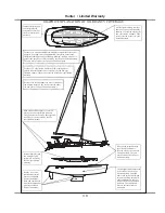
Page 214: ...Notes Hunter 36 Maintenance 14 14 ...
Page 215: ...Exterior Lifting Points g Hunter 36 Maintenance 14 15 ...
Page 216: ...Hunter 36 Maintenance 14 16 This Page Intentionally Left Blank ...
Page 217: ...Hunter 36 Maintenance 14 17 Exterior Lifting Points Saildrive g ...
Page 218: ...Hunter 36 Maintenance 14 18 This Page Intentionally Left Blank ...
Page 219: ...Glossary Glossary H36 H36 Chapter 15 Chapter 15 V1 040107 P N 1031378 ...


