Hunter 36 • Boating Safety
4.5
diffuses in the air much more rapidly than other gasses
that are detectable by the human senses. The weight of
CO is about the same as air so it does not rise or fall like
other gasses but will distribute itself throughout the boat.
CO is produced any time a material containing carbon is
burned. In boating, these materials include, but are not
limited to, gasoline, diesel fuel, or propane. All carbon
based fuels produce varying amounts of CO, depend-
ing on their carbon content. Gasoline is high in carbon
and, therefore, produces lower levels of CO. However,
the exhaust of all engines and generators as well as any
open flame device, produce CO and the same precau-
tions should be taken regardless of the type of fuel.
4.2.3 How Carbon Monoxide Can Enter Your Boat
Any device that burns fuel creates Carbon Monoxide. For
example, a propane cook-top or a space heater are both
potential sources for CO. But the most serious danger
comes from the gasoline engines and generators aboard
your own and neighboring boats. There are four basic
ways that CO from a running engine or generator can
enter your boat.
The “station wagon effect” results from the aerodynamics
of deck cabins and flying bridges. With the boat under-
way, the air flow over the top forms a low pressure area
behind the cabin or transom which can suck exhaust gas-
ses into the cockpit and the cabin inefficient trim angles
also can cause the station wagon effect.
4.2.4 Symptoms of Carbon Monoxide Poisoning
Most important is to know the causes, study the symp-
toms, and be trained in the emergency care. This is
the best way to avoid, understand, and respond to any
Carbon Monoxide emergency:
One or more of the following symptoms can signal the
adverse effects of Carbon Monoxide accumulation. The
order of this list is generally the sequence of symptoms.
However, the number of symptoms and the order of their
appearance may change for different people.
Watering and Itching eyes
Tightness in the chest
Flushed Appearance
Ringing in the ears
Throbbing Temples
Inattentiveness Convulsions
Drowsiness
Headache
Dizziness
Vomiting
Collapse
Nausea
Fatigue
4.2.5 Effects of Carbon Monoxide
When inhaled, Carbon Monoxide is absorbed by the
lungs and reacts with the blood hemoglobin to form
carbon hemoglobin, which reduces the oxygen carrying
capacity of the blood. The result is a lack of oxygen
for the tissues, causing subsequent tissue death and, if
prolonged, death of the individual. Carbon Monoxide in
high concentrations can be fatal in a matter of minutes.
Even lower concentrations must not be ignored because
the affects of exposure to CO are cumulative and can
be just as lethal. Certain health related problems and
age increases the effects of CO. People who smoke or
are exposed to high concentrations of cigarette smoke,
consume alcohol, or have lung or heart disorders are
particularly susceptible to an increase in the effects from
CO. However, the health of all of the boat’s occupants
should be considered. Physical exertion accelerates the
rate at which the blood absorbs CO. The early effects
of CO poisoning are easy to overlook because they are
similar to the effects of other boating related stress such
as eye strain, fatigue, sun exposure, seasickness, or
alcohol consumption. But, as the concentration of CO in
the air increases, it has increasingly adverse effects on
your health.
4.2.6 When Overcome by Carbon Monoxide
When someone falls victim to Carbon Monoxide poison-
ing, fast and responsive action is crucial. Know the symp-
toms. The earlier the effects of CO are detected, the
better the chances for recovery. The following list shows
the sequences of events that must be done in an effort to
revive a CO victim:
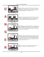
Evacuate, Ventilate, Investigate, complete the Carbon
Monoxide poisoning action sequence
Move the victim to fresh air.
Administer oxygen if available. If the victim is not
breathing, perform artificial resuscitation per approved
CPR procedures until medical help arrives and takes
over. Prompt action can mean the difference between
life and death.
Ventilate the area.
Investigate the source of CO and take corrective
action.
•
•
•
•
•
Summary of Contents for H36
Page 1: ...Operator s Operator s Manual Manual H36 H36 V1 040107 P N 1031378 ...
Page 2: ......
Page 9: ...Introduction Introduction H36 H36 Chapter 1 Chapter 1 V1 040107 P N 1031378 ...
Page 14: ...Hunter 36 Introduction 1 6 Notes ...
Page 15: ...V1 040107 P N 1031378 and Documents Documents Forms Forms H36 H36 Chapter 2 Chapter 2 ...
Page 26: ...Hunter 36 Documents and Forms Maintenance Log Date Maintenance Performed Hourmeter 2 12 ...
Page 27: ...Hunter 36 Documents and Forms 2 13 Date Maintenance Performed Hourmeter Maintenance Log ...
Page 33: ...Hunter 36 Documents and Forms 2 19 Spare Parts List ...
Page 34: ...Hunter 36 Documents and Forms Dates of practice drills and onboard safety inspections 2 20 ...
Page 35: ...Hunter 36 Documents and Forms 2 21 My personal preferences for maintenance items safety gear ...
Page 36: ...Hunter 36 Documents and Forms Notes 2 22 ...
Page 37: ...DC 071609 Limited Limited Warranty Warranty Chapter 3 Chapter 3 ...
Page 38: ...This Page Intentionally Left Blank Hunter Limited Warranty 3 2 ...
Page 47: ...Boating Boating Safety Safety H36 H36 Chapter 4 Chapter 4 V1 040107 P N 1031378 ...
Page 68: ...Hunter 36 Boating Safety 4 22 Notes ...
Page 69: ...Chapter 5 Chapter 5 Fuel Fuel Systems Systems H36 H36 V1 040107 P N 1031378 ...
Page 75: ...Fig 5 7 A Quick Fuel Filter Reference Hunter 36 Fuel Systems 5 7 ...
Page 82: ...Notes Hunter 36 Fuel Systems 5 14 ...
Page 83: ...Underwater Underwater Gear Gear H36 H36 Chapter 6 Chapter 6 V1 040107 P N 1031378 ...
Page 92: ...Hunter 36 Underwater Gear 6 10 Notes ...
Page 93: ...DC Electric DC Electric Systems Systems H36 H36 Chapter 7 Chapter 7 V1 040107 P N 1031378 ...
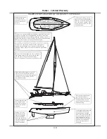
Page 103: ...Hunter 36 DC Electric 7 11 7 8 BASIC DC POWER SUPPLY SYSTEM DIAGRAM ...
Page 104: ...Hunter 36 DC Electric 7 12 Notes ...
Page 106: ...Hunter 36 DC Electric 7 14 Notes ...
Page 108: ...Hunter 36 DC Electric 7 16 Notes ...
Page 109: ...AC Electric AC Electric Systems Systems H36 H36 Chapter 8 Chapter 8 V1 040107 P N 1031378 ...
Page 118: ...This Page Intentionally Left Blank Hunter 36 AC Electric Systems 8 10 ...
Page 119: ...Hunter 36 AC Electric Systems 8 11 7 8 AC DC Electric Power Supply Diagram pp y g ...
Page 120: ...Hunter 36 AC Electric Systems 8 12 This Page Intentionally Left Blank ...
Page 121: ...Hunter 36 AC Electric Systems 8 13 Notes ...
Page 122: ...Hunter 36 AC Electric Systems 8 14 Notes ...
Page 123: ...Water Water Systems Systems H36 H36 Chapter 9 Chapter 9 V1 040107 P N 1031378 ...
Page 130: ...Hunter 36 Water Systems 9 8 This Page Intentionally Left Blank ...
Page 132: ...Hunter 36 Water Systems 9 10 This Page Intentionally Left Blank ...
Page 133: ...Hunter 36 Water Systems 9 11 Notes ...
Page 134: ...Hunter 36 Water Systems 9 12 Notes ...
Page 135: ...Waste Waste Systems Systems H36 H36 Chapter 10 Chapter 10 V1 040107 P N 1031378 ...
Page 144: ...This Page Intentionally Left Blank Hunter 36 Waste and Sanitation Systems 10 10 ...
Page 146: ...This Page Intentionally Left Blank Hunter 36 Waste and Sanitation Systems 10 12 ...
Page 148: ...This Page Intentionally Left Blank Hunter 36 Waste and Sanitation Systems 10 14 ...
Page 149: ...Sump Pump Layout Grey Water p p y y Hunter 36 Waste and Sanitation Systems 10 15 ...
Page 150: ...This Page Intentionally Left Blank Hunter 36 Waste and Sanitation Systems 10 16 ...
Page 152: ...This Page Intentionally Left Blank Hunter 36 Waste and Sanitation Systems 10 18 ...
Page 153: ...Hunter 36 Waste and Sanitation Systems 10 19 Notes ...
Page 154: ...Hunter 36 Waste and Sanitation Systems 10 20 Notes ...
Page 164: ...Hunter 36 Engines and Transmissions 11 10 This Page Intentional Left Blank ...
Page 165: ...V1 040107 P N 1031378 Sails Sails Rigging H36 H36 Chapter 12 Chapter 12 and and ...
Page 171: ...Hunter 36 Sails and Rigging 12 7 Standing Rigging Details Standard ...
Page 172: ...Hunter 36 Sails and Rigging 12 8 Standing Rigging Details Furling ...
Page 173: ...Hunter 36 Sails and Rigging 12 9 Mast Upper Spreader Tip Details pp p p H A B C D E F G ...
Page 174: ...Hunter 36 Sails and Rigging 12 10 C A B D E F G H J K I Mast Lower Spreader Tip Details p p ...
Page 175: ...Hunter 36 Sails and Rigging 12 11 Standing Rigging Details ...
Page 179: ...Hunter 36 Sails and Rigging 12 15 Typical Boom Reefing Layout yp g y ...
Page 180: ...Hunter 36 Sails and Rigging 12 16 Rope Vang Details Standard Vang Details ...
Page 181: ...Hunter 36 Sails and Rigging 12 17 Rigid Vang Details Optional Vang Details ...
Page 184: ...Hunter 36 Sails and Rigging 12 20 JIB LINE TIES OFF ON CLEAT Jib Furling Line Layout ...
Page 185: ...Hunter 36 Sails and Rigging 12 21 Bridle Configuration ...
Page 186: ...Hunter 36 Sails and Rigging 12 22 Optional Mainsheet Traveler Layout ...
Page 190: ...Hunter 36 Sails and Rigging 12 26 Optional Spinnaker Layout ...
Page 191: ...Hunter 36 Sails and Rigging 12 27 Notes ...
Page 192: ...Hunter 36 Sails and Rigging 12 28 Notes ...
Page 193: ...Getting Getting Underway Underway H36 H36 Chapter 13 Chapter 13 V1 030107 P N 1031378 ...
Page 200: ...Hunter 36 Getting Underway 13 8 Notes ...
Page 201: ...Maintenance H36 H36 Chapter 14 Chapter 14 V1 040107 P N 1031378 ...
Page 214: ...Notes Hunter 36 Maintenance 14 14 ...
Page 215: ...Exterior Lifting Points g Hunter 36 Maintenance 14 15 ...
Page 216: ...Hunter 36 Maintenance 14 16 This Page Intentionally Left Blank ...
Page 217: ...Hunter 36 Maintenance 14 17 Exterior Lifting Points Saildrive g ...
Page 218: ...Hunter 36 Maintenance 14 18 This Page Intentionally Left Blank ...
Page 219: ...Glossary Glossary H36 H36 Chapter 15 Chapter 15 V1 040107 P N 1031378 ...

