background image


The Sensitivity Menu allows you to “bias” this automatic setting up or down based on personal 
preference. You can select a bias of +5 or –5, for 11 different bias settings. A bias setting of “0” has no 
effect on the automatic function. A +3 setting selects a sensitivity setting three steps higher than the unit 
would normally select, so even the smallest returns are displayed on-screen. 
 
A setting of –2 sets the sensitivity two steps below what the unit would normally select, so only the largest 
targets or other returns are displayed. 
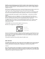
 
Range 
 
The Wide One Deep adjusts the depth range automatically, so the bottom return is displayed at the 
bottom 1/3 of the display. This leaves the top 2/3 to display anything between the surface and the bottom. 
As your boat moves over deeper or shallower water the unit adjusts the depth range of the display to 
keep the bottom return in the same general area on the screen. 


You may, however, choose to control this range adjustment manually. By pressing ENTER, you can 
select manual operation, meaning the unit will no longer adjust the depth range automatically. The depth 
range selected is controlled by the UP and DOWN arrow buttons. The depth ranges are 0-15’, 30’, 60’, 
120’, 180’, 240’, 360’, 480’, & 600’. 
 
If you alter the depth range, Manual operation is automatically selected and the area beneath the bottom 
will no longer be blackened in. 


Summary of Contents for Wide One Deep

Page 1: ...our number listed in the Customer Support section INSTALLATION OVERVIEW Your Humminbird fishfinder consists of two primary components to install the control head and the transducer The control head c...

Page 2: ...should the boat strike debris in the water or when trailering As an alternative to transom mounting it is possible on many fiberglass hulled boats to glue the transducer on the inside of the boat hull...

Page 3: ...other surface Trolling Motor Mounting The standard transducer can also be adapted to mount on most trolling motors using a different accessory kit This accessory includes a bracket and hose clamp that...

Page 4: ...minbird fishfinder The installation guide included on the next few pages provides detailed step by step instructions for installation of the control head and transducer For transom mount transducer in...

Page 5: ...the propeller s This turbulent water is normally confined to areas immediately aft of ribs strakes or rows of rivets on the bottom of the boat and in the immediate area of the propeller s Figure 1 On...

Page 6: ...g a 5 32 4mm bit drill the two holes to a depth of approximately 1 3cm On fiberglass hulls it is best to start with a smaller bit and use progressively larger drill bits to reduce the chance of chippi...

Page 7: ...ation after high speed testing 1 First adjust the pivot angle of the transducer body so its length is parallel with the length of hull of the boat Then pivot the transducer down so the rear is about 1...

Page 8: ...erference If the cable is too short extension cables are available to extend the transducer cable up to a total of 50 15 m Call Humminbird Customer Support for more information Follow these steps to r...

Page 9: ...hull to install the transducer Consider the following to find the best location Observe the outside of the boat hull to find the areas that are mostly free from turbulent water Avoid ribs strakes and...

Page 10: ...dry the mounting surface If the surface is excessively rough it may be necessary to sand the area to provide a smooth mounting surface Ensure the mounting area is clear and dry 3 Mix an ample quantit...

Page 11: ...y supported to protect the fishfinder from excessive wave shock and vibration and provide visibility while in operation The mounting area should allow sufficient room for the unit to pivot and swivel...

Page 12: ...holes Figure 22 Note if the cables must pass through the mounting surface at a different location drill the 1 25mm hole at that location and pass the cables through from underneath Also you must break...

Page 13: ...ll the excess cable from beneath the mounting surface so the connector holder aligns with the mounting holes on the front of the mounting bracket Figure 27 3 Snap the support plate to the rear of the...

Page 14: ...rmal operation unless you choose another option If you do not press any button before the timer reaches 0 the normal operation screen is displayed If the boat is in water sonar data appears If the bot...

Page 15: ...usts the depth range to a setting most appropriate for that depth The bottom will usually be shown about 2 3 of the way down the display The transmitted sonar signal travels downwards and is reflected...

Page 16: ...hin the menu Holding an Arrow button down will cause the unit to continue to make the adjustment until a limit is reached and a continuous chirp is heard DOWN ARROW selects the next smaller adjustment...

Page 17: ...automatically so the bottom return is displayed at the bottom 1 3 of the display This leaves the top 2 3 to display anything between the surface and the bottom As your boat moves over deeper or shall...

Page 18: ...0 to 480 depth range is used the zoom range will be 30 and if the 600 range is in use the zoom range will be 60 To enable zoom adjust the depth of the zoom range first using the UP and DOWN Arrow butt...

Page 19: ...on screen To enable Fish Alarm use the UP and DOWN arrow buttons to adjust the size return you want to be alerted to large fish only large and medium size fish or all fish Then press ENTER to enable...

Page 20: ...the update rate of the display There are five rate settings available You may speed up or slow down the rate to match your personal preference To present the most accurate representation of the terrai...

Reviews: