


INSTALLATION
CONTROL HEAD INSTALLATION
CONTROL HEAD INSTALLATION
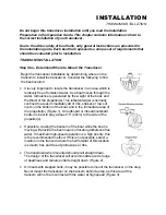
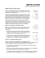
Step One - Determine Where to Mount
Begin the installation by determining where to mount the control head. Consider the
following to determine best location:
•
The cables for power, transducer and temp/speed accessories (if applicable) should
be installed first and must reach the mounting location. Extension cables are
available.
•
There are two ways to route the cables to the unit: through a
hole in the mounting surface underneath the mounting bracket
or from a hole outside the mounting bracket. Routing the cables
down under the mount provides maximum weather protection;
however this is not always feasible if the area under the
fishfinder is inaccessible. In this case, route the cables through
a hole at another location and cover with the supplied hole
cover.
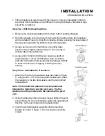
•
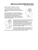
The mounting surface should be adequately supported to
protect the fishfinder from excessive wave shock and vibration,
and provide visibility while in operation.
•
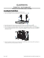
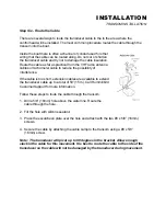
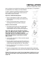
The mounting area should allow sufficient room for the unit to
pivot and swivel freely, and for easy removal and installation
(Figures 18-19).
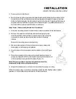
Step Two - Connect the Power Cable to the Boat
A 6’ (2m) long power cable is included to supply power to the
fishfinder. You may shorten or lengthen the cable using 18 gauge
multi-stranded copper wire.
CAUTION: Some boats have 24 or 36 volt electric systems. Be
sure your unit is connected to a 12 VDC power supply.
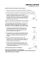
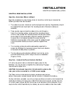
The Power can be connected to the boat's electrical system at two
places: a fuse panel, usually located near the console, or directly to the battery.
If a fuse terminal is available, use crimp-on type electrical connectors (not included) that
match the terminal on the fuse panel. Attach the black wire to ground, and the red wire
to 12 VDC power (Figure 20). Be sure to use a one amp fuse in the connection. If you
must wire the control head directly to a battery, be sure to install an inline fuse holder