background image


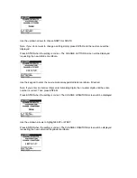
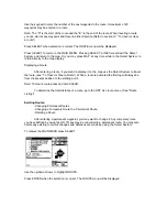
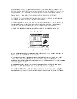
Use the up/down arrows to highlight WAYPOINT 
 
Press ENTER when the selection is correct. The WAYPOINT menu will be displayed. 


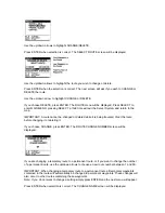
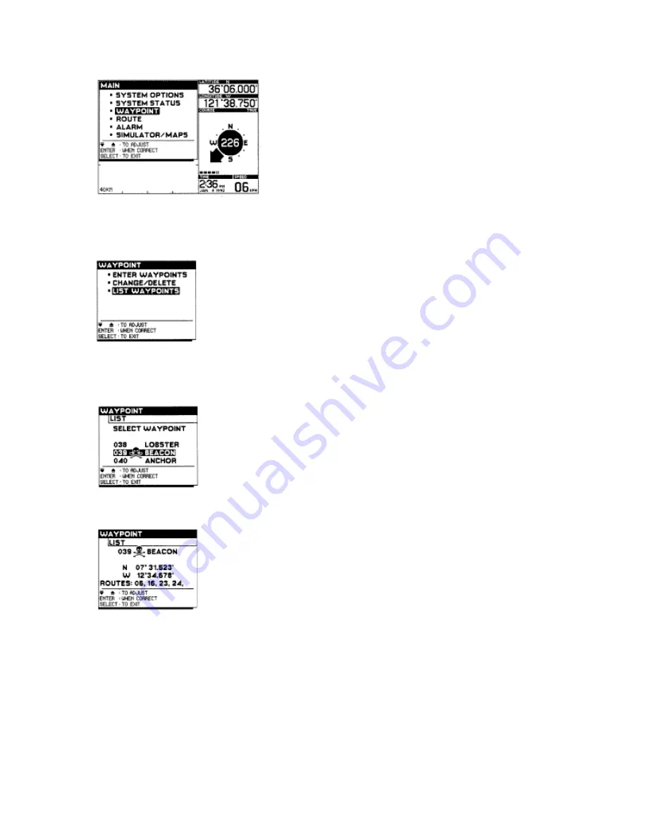
Use the up/down arrows to highlight LIST WAYPOINTS. 
 
Press ENTER when selection is correct. A listing of all stored waypoints will be displayed. 


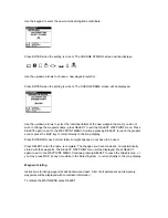
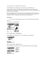
Use the up/down arrows to list additional waypoints. 


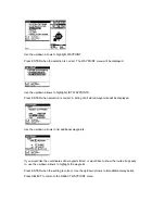
If you would like the coordinates of a waypoint listed, or would like to know the routes it appears 
in, use the up/down arrows to highlight the waypoint. 
 
Press ENTER when the setting is correct. Use the up/down arrows to list additional waypoints. 
 
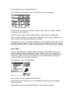
Press SELECT to return to the SELECT WAYPOINT menu. 
 

Summary of Contents for NS 10

Page 1: ......

Page 2: ...nt to the NS 10 for display The NS 10 uses this raw information to provide many options for graphic display Your position is superimposed onto digital maps stored in the system s memory Figure 1 shows...

Page 3: ...s Phillips head screw driver Ruler or measuring tape Flat head screw driver Pen or pencil 12 volt DC power source your boat s battery 1 amp fuse if you connect the unit directly to the battery Silicon...

Page 4: ...hardware kit The power cable hole cover and the 40 foot receiver cable Refer to Figure 6 If the receiver cable is not long enough to reach the desired mounting location an extension cable is availabl...

Page 5: ...urn the receiver to tighten fully 8 Connect the extension cable to the receiver cable and route to the NS 10 Note If the mounting surface is rough or irregular use silicone sealant to ensure a water t...

Page 6: ...steners are provided to seal that hole as well Additional Mounting Methods Using Other Marine 1 14 Hardware Most marine distributors carry a wide variety of antenna mounting hardware The NS 10 receive...

Page 7: ...e routing the cables through the slots but do not fully tighten the mounting screws until you determine how much cable to leave exposed 9 Insert the cable connectors into the corresponding numbered co...

Page 8: ...ble This will prevent the battery voltage to the NS 10 from becoming too low while starting the boat engine Optional Flush Mount Figure 7 shows a flush mounted NS 10 control head If you would like to...

Page 9: ...ion or steering information Numeric Longitudinal Display This area displays the numeric longitude coordinate of your present position Numeric Latitude Display This area displays the numeric latitude c...

Page 10: ...visible on the screen P STOR Stores your present position as a temporary waypoint or stores the position of the cursor when it is in use STEER Provides detailed steering information when a route has...

Page 11: ...hen DGPS is displayed the NS 10 is operating in the differential mode and latitude longitude values should be within DGPS tolerances 3 NMEA OUTPUT This connector with the supplied cable allows the NS...

Page 12: ...cle at home Note AC adapters are not provided with some NS 1o International models This is especially convenient when learning to use the NS 10 or for entering a long multileg route from charts Refer...

Page 13: ...mode will show Error If you are using the NS 10 with the AC adapter ignore this message as the receiver is not necessary for simulator operation If the receiver is connected and this message appears R...

Page 14: ...ontrol input while this occurs except power light the Select System and zoom in zoom out Refer to Figure 12 If your position is stationary when the NS 10 identifies your location and first draws the m...

Page 15: ...of any keys because they represent the equivalent of fifty or more discrete function buttons Using the Select System enables you to access dozens of unique features in addition to adjusting the setti...

Page 16: ...u Heading Title of the menu that you are currently using Options These are the options available to you under the menu that you are using Key Functions This area contains references to key functions a...

Page 17: ...as before until you have made all necessary adjustments If your adjustments are complete press SELECT twice to return to the MAIN MENU Press SELECT a third time to exit the Select System and return to...

Page 18: ...is updated once per second On medium the information is updated every three seconds with speed and heading being averaged over the last three seconds The SLOW setting has a 5 second update and averagi...

Page 19: ...Press ENTER when the setting is correct You will be asked to choose a secondary station Use the up down arrows to choose the first secondary station Press ENTER when setting is correct You will be ask...

Page 20: ...he waypoint DISPLAY CONTRAST Retrieve the MAIN MENU by pressing the SELECT key Use the up down arrows to highlight SYSTEM OPTIONS Press ENTER when the setting is correct The SYSTEM OPTIONS menu will b...

Page 21: ...the Select System will return the map to the graphic area Pressing MAP when the map is already in the graphic area displays the Map Setup 1 menu pressing again displays the Map Setup 2 menu for addit...

Page 22: ...e boat to align the projected course line with your destination or the next point in your route The map will rotate and scroll to give an accurate moving map of your route Note The maximum range in th...

Page 23: ...r the picked waypoint This feature is extremely valuable when previewing your route or viewing waypoints some distance from your present position Pressing CLEAR will clear the cursor or pick mode and...

Page 24: ...st and it provides a very quick and accurate way to navigate to the cursor position To Scroll the Map The cursor may also be used to scroll the map on the display screen When the cursor reaches the bo...

Page 25: ...WAYPOINT USING PICK The PICK key is used to gain more information about previously stored waypoints Waypoints are shown in the graphics areas of the display as a small box Temporary waypoints are sto...

Page 26: ...has been stored in the general area as shown in figure 22 PICK is ideal for illuminating all the waypoints represented by the multiple waypoint symbol Simply continue to press the cursor and each of t...

Page 27: ...indicated by the mode indicator at the lower part of the graphics area It will usually be shown in conjunction with another mode indicator i e PICK or CURSOR Pressing CLEAR will clear the leftmost mo...

Page 28: ...ear in the multi function display box The display will provide information on your present course vs your intended course with instruction for getting back on course and other navigation information h...

Page 29: ...points Entering a New Waypoint Press SELECT to retrieve the MAIN MENU Use the up down arrows to highlight WAYPOINT Press ENTER when setting is correct The WAYPOINT menu will be displayed Three options...

Page 30: ...Glossary Press ENTER when the selection is correct The SELECT LATITUDE screen will be displayed requesting a numerical coordinate Note You may always refer to the right of the display to get informat...

Page 31: ...when the setting is correct The SELECT SYMBOL screen will be displayed Note It is not necessary to assign a symbol to a waypoint Symbols simply help you remember the purpose of a stored point Use the...

Page 32: ...ng Waypoints Changing Permanent Waypoints Changing a Temporary Waypoint to a Permanent Waypoint Deleting a Waypoint After entering a permanent waypoint you may want to change or delete it Any temporar...

Page 33: ...menu will be displayed Note A waypoint that is part of a route cannot be deleted or changed until it is taken out of the route or until the route is deleted If you choose CHANGE press ENTER The CHANG...

Page 34: ...keypad to enter the new numerical waypoint latitude coordinate if desired Note If you enter an incorrect digit enter remaining digits then re enter digits until the entire number is correct Then pres...

Page 35: ...CT to reach the graphic area or press the MAP key to return directly to the map display Press ENTER after each correct letter All eight spaces do not have to be used Press SELECT when the name is comp...

Page 36: ...orrect A listing of all stored waypoints will be displayed Use the up down arrows to list additional waypoints If you would like the coordinates of a waypoint listed or would like to know the routes i...

Page 37: ...more permanent waypoints The NS 10 has the capability to store up to 50 permanent routes A maximum of 20 waypoints can be contained in a route You may store a permanent route by using the Select Syste...

Page 38: ...oute number between 1 and 50 Press ENTER when the selection is correct The SELECT NAME screen will be displayed It is not necessary to store a name with your route this is just another way to help ide...

Page 39: ...ant to display it on the map use the Select System to travel the route see To Travel or Clear a Route When a route is activated the first leg will always be from the present position to the starting p...

Page 40: ...changed or deleted while it is being traveled Clear the route before changing it or deleting it If you choose CHANGE press ENTER The ROUTE CHANGE NUMBER screen will be displayed If you are changing a...

Page 41: ...ADD WAYPOINTS or DELETE WAYPOINTS Use the up down arrows to highlight ADD WAYPOINTS or DELETE WAYPOINTS Press ENTER when the selection is correct If you selected ADD WAYPOINTS go to the ADD WAYPOINTS...

Page 42: ...ect System to return directly to the map display To Travel or Clear a Route The Select System in conjunction with the STEER key will allow you to gain valuable information about traveling a route Refe...

Page 43: ...n the SELECT ROUTE TO TRAVEL screen will be displayed Use up down arrows to highlight the route that you wish to travel Press ENTER when the selection is correct The SELECT START POINT screen will be...

Page 44: ...ode will be activated The GO TO key cannot be used to add waypoints to a route when a route from the Select System is being traveled The CLEAR key can be used to clear the route without using the Sele...

Page 45: ...sition you can use 1 The cursor with the DIST key or 2 The PICK with the DIST key Using the Cursor with the DIST Key Press CLEAR to remove any existing modes from the mode indicator area Press the cur...

Page 46: ...will sound when you are within the specified range of your destination or interim waypoint It will only sound while you are traveling a temporary or permanent route OFF COURSE This alarm will only sou...

Page 47: ...section V Real World Applications Press ENTER when the setting is correct This will return you to the ALARM menu Use the up down arrows to select your next parameter for adjustment Continue as before...

Page 48: ...ing just as it was when it was purchased Clearing everything from memory will allow you to begin navigating in a new area with all new settings If you do not want to clear all entered items you may cl...

Page 49: ...stem Options Note Depressing the CLEAR key for three seconds will clear all temporary waypoints and routes but it will not clear permanent waypoints and routes Datalog Screen The Datalog screen displa...

Page 50: ...elect System and return to the map Or you may press MAP at any time while in the Select System to return directly to the map display System Status There are many different ways to display system perfo...

Page 51: ...DLE there are no satellites visible on this channel 3 SATELLITE NUMBER This is the identification number of the satellite being tracked 4 C N C N is the measure of the satellite s carrier signal to no...

Page 52: ...r Set Up Options Additional user setup options can be accessed by pressing the MAP key while in the graphic area Because these menus are adjusted frequently they may be accessed directly without enter...

Page 53: ...er needing adjustment Continue as before until you have made all necessary adjustments If your adjustments are complete press MAP to returned to the graphic area The following adjustment menus are ava...

Page 54: ...t the NS 10 is set to the same map datum Use the up down arrows to select your setting preference then press ENTER Use the up down arrows to select the interval that your history points are plotted Fo...

Page 55: ...ll be in the opposite direction 180 difference from the bearing to the cursor For example if the bearing to the cursor is 340 the map offset would be 160 You should do this for multiple points to ensu...

Page 56: ...nently store waypoints and routes prior to travel To use the NS 10 without a receiver simply connect the AC adapter to the power 1 connector on the rear of the NS 10 and plug the transformer into a wa...

Page 57: ...off or disconnected To turn on SIMULATOR or MAP PREVIEW without changing the origin use the up down arrows to highlight SIMULATOR or MAP PREVIEW Press ENTER when selection is correct The simulator sho...

Page 58: ...to help you reach your destination This is done in two ways graphically the route appears in the graphics area of the display as a line showing your position your destination and any interim points a...

Page 59: ...he associated screen displays on the following pages show the NS 10 in the forward looking and top down view The following displays correspond to positions 1 5 in Figure 29 The steering screen is acti...

Page 60: ...d however your boat s course is now 052 degrees In order to return to your planned route you should steer left How severely you correct your course will depend on surrounding hazards If no hazards are...

Page 61: ...ndicator appears and the desired course line begins to drift to the right of the steering indicator If the turn is continued a point is reached where it would be more expeditious to continue the left...

Page 62: ...When nearing your final destination the NS 10 will continue to provide steering information to the exact waypoint until the ARRIVAL ALARM is cleared Using the NS10 in an Emergency In the event of an o...

Page 63: ...hree seconds Maintenance Your Humminbird NS 10 is designed to give you years of trouble free operation with virtually no maintenance Follow the simple procedures listed below to ensure your NS 10 cont...

Page 64: ...t address listed on the rear cover of this manual 3 The NS 10 turns on but displays no position read out If the initial screen shows a self test failure your unit may need to be serviced Try to restar...

Page 65: ...sales receipt will be required Accessories not manufactured under the Humminbird trade name are not covered by our warranty The customer is responsible for shipping charges to Humminbird Humminbird w...

Page 66: ...MBytes RAM 256 KBytes Memory Back up Internal 3 5 V Lithium Battery Communication Output NMEA 0183 Back Light 5 Levels Operational Temp Range 10 to 70 Celsius Display Super Twist LCD Viewing Area 4 5...

Page 67: ...Options NMEA The NS 10 has the capability of outputting position speed and course information to other electronic devices such as plotters radars autopilots etc The NS 10 uses a standard format for o...

Page 68: ...at at 4800 or 9600 baud Glossary ALL CLEAR DEFAULT SETTING No The last option on the user set up menu is called ALL CLEAR This is a powerful menu used to clear all user entered items from the permanen...

Page 69: ...me display to local time DIRECTIONAL ARROWS controls the position and movement of the cursor function as well determining the direction of PICK COURSE your actual direction of travel measured in degre...

Page 70: ...te however if you choose you may reverse this by selecting white Try it both ways and decide which option works best for you LAT LON GRIDLINES Default setting off You have the option of displaying nea...

Page 71: ...tation with these settings is the best way to find the option that suits you The NS 10 allots sufficient memory to store 240 position points so when selecting ALL be aware that after recording two hou...

Page 72: ...fast With this setting on fast the NS 10 updates time and displays a course and position update once per second With a medium setting the information is updated every three seconds with speed and head...

Page 73: ...29 HELP 14 23 MAP 14 PICK 14 28 44 59 P STOR 14 27 STEER 14 30 TEXT 14 23 VIEW 14 24 ZM IN ZM OUT 14 25 Display contrast 22 Distance DIST to a waypoint using PICK 44 DIST to cursor 44 from present po...

Page 74: ...power Origin 54 Offset UTC 20 65 P PICK 14 28 44 59 PDOP49 P STOR 14 27 Position fix 6 17 Position lat lon 52 53 Power trouble shooting 60 turning on and off 16 R Range 25 Receiver additional mounts...

Page 75: ...22 distance speed 19 heading 19 20 land mass 51 lat Ion gridlines 51 NMEA output 19 20 plotter history 51 52 position 19 21 UTC offset 19 20 update averaging 19 20 System status 49 T TEXT 14 23 Time...

Reviews: