background image

Chapter 3 • The User Interface

1031484-0001 Revision 2

47

The Connectivity Test 
Menu

You may lose connectivity to a particular server due to the 
Internet and/or the satellite network being heavily loaded or due 
to the server being down. If possible, check connectivity to some 
other server on the Internet to ensure it is not a server specific 
problem. Follow the procedure below for troubleshooting:

Network Operations Center

(NOC) Connectivity

Use the Connectivity Test from the left pane to check 
connectivity to the DIRECWAY NOC.

Note:

You may want to open a second browser window to be able 

to access this help page while conducting the Connectivity Test.

1. Click on 

Connectivity Test

 on the left hand side of the 

User 

Interface

. The screen in Figure 40 appears.

2. Run the test. A message will appear, informing you if the test 

was successful.
If the connectivity test succeeds, try pinging the NOC Router 
Address from the computer. This address can be obtained 
from the 

System Information

 page. See 

System Information


on page 45.
If this succeeds, skip to the Internet Connectivity test below.
If this fails, the default gateway is probably not set correctly 
on the computer’s network settings. The default Gateway 
should be the Gateway IP address. Fix this in the computer's 
network settings and repeat the connectivity test.
If the test still fails, power-cycle the DW4020 by unplugging 
the power cord from the wall outlet and plugging it back in. If 
this doesn't fix the problem, call Customer Care.
If the connectivity test fails, check the DW4020 configuration 
via the System Information page.

Summary of Contents for DW4020

Page 1: ...BUSINESS SPECIALISTS www groundcontrol com DW4020 INSTALLATION GUIDE Ground Control 800 773 7168 ...

Page 2: ...11717 Exploration Lane Germantown MD 20876 Tel 301 428 5500 Fax 301 428 1868 2830 1031484 0001 Revision 3 October 24 2002 DW4020 Installation Guide ...

Page 3: ...nd completeness of the material in this document Hughes Network Systems Inc shall not be liable for errors contained herein The information in this document is subject to change without notice Hughes Network Systems Inc makes no warranty of any kind with regard to this material including but not limited to the implied warranties of merchantability and fitness for a particular purpose Trademarks Al...

Page 4: ...ce may not cause harmful interference and 2 this device must accept any interference received including interference that may cause undesired operation Responsible Party s name Hughes Network Systems Inc Address 11717 Exploration Lane Germantown MD 20876 Telephone 866 DIRECWAY 347 3292 Trade Name HUGHES Type of Equipment Satellite Transmit and Receive Modem VSAT Ethernet Appliance Model Numbers DW...

Page 5: ... iv 1031484 0001 Revision 3 ...

Page 6: ...allation methods 6 Summary of DW4020 installation process 6 Antenna installation 6 Installing DIRECWAY installation software on installer laptop 8 Installing the software 9 Installing the system using a modem 11 The power supply 12 Assembling the components modem installation method 13 Connect Ethernet power up and read the Gateway LED display 17 Obtain IP address and test Ethernet connection 18 T...

Page 7: ...nu 49 The Settings Menu 49 The Help Menu 51 myDIRECWAY 52 Software updates and the User Interface 52 Chapter 4 DW4020 LEDs and troubleshooting 53 The DW4020 LEDs 53 DW4020 LEDs status 54 Normal operation no transmit or receive 54 Normal operation data being sent and received 55 Problem receive modem READY LED not on 55 Transmit modem READY LED not lit 57 Gateway LEDs not lit 58 Gateway LEDs flash ...

Page 8: ...l operation data being sent and received 88 Problem receive modem READY LED not on 88 Transmit modem READY LED not lit 90 Gateway LEDs not lit 91 Gateway LEDs flash receive modem READY LED off or flashing 92 LED blinking indicating status codes 92 Ethernet port LEDs 94 Communicating with the Gateway through the serial port 95 Connecting the Gateway and laptop 95 Configuring Hyperterminal or termin...

Page 9: ...Display active routing table 112 Reset history 112 Appendix D Configuring the installer laptop for IP addressing 113 Windows 98SE and ME 113 Windows 2000 116 Windows XP 118 Appendix E Installation checklist 121 Installation summary and checklist 121 Index 123 ...

Page 10: ...nual This section introduces the various types of warnings used in this manual to alert you to possible safety hazards DANGER Indicates an imminently hazardous situation which if not avoided will result in death or serious injury WARNING Indicates a potentially hazardous situation which if not avoided could result in death or serious injury CAUTION Indicates a potentially hazardous situation which...

Page 11: ... Important safety information x 1031484 0001 Revision 2 ...

Page 12: ...n call center operators Organization and updates This manual is organized into the following chapters Major changes from Revision 1 are identified Chapter 1 Introduction gives an overview of the DW4020 and its components The description of IP addressing is moved to an appendix Chapter 2 Installing the indoor equipment provides information regarding installing and configuring the DW4020 The modem m...

Page 13: ...ates the names of command buttons that execute an action The system displays the following Are you ready Indicates all system messages and prompts as the system displays them Type exit Indicates operator input Enter a value in the Time field Indicates the names of fields on windows Retrieve the following file O template techman_r3 Indicates file names or file paths referenced in the manual Press A...

Page 14: ...nections through a single DIRECWAY terminal It is composed of three stackable components as shown in Figure 1 Receive modem also sometimes referred to as the Indoor Receive Unit IRU Transmit modem also sometimes referred to as the Indoor Transmit Unit ITU Gateway GWH Note Revision 1 of this manual referred to the DW4020 as the Gateway and the Gateway as the Gateway host This terminology has change...

Page 15: ...independent of operating platforms It can also be used with devices other than computers such as point of sale POS terminals or credit verification devices Characteristics and identification of equipment The part number label is located on the rear of the unit Table 1 shows the hardware characteristics of the DW4020 Table 2 shows the physical characteristics of the unit Table 3 shows the cable req...

Page 16: ...J 45 Main Memory 32MB Flash Memory 8MB Serial Port Asynchronous RS232 USB Port One USB 1 1 Type A Table 2 DW4020 physical characteristics Characteristic Value Physical Dimensions Height Width Depth Weight 5 75 inches 6 5 inches 8 8 inches 4 0 lbs Electrical Requirements Input line voltage Input line frequency Current Required 90 264 V 2A max 50 60 HZ AC 100 W typical ...

Page 17: ...owever you can also use standard RG 6 and ground according to the Code or the instructions in the antenna installation manual Recommended cable specifications for One Way and Two Way Systems Cable length from satellite dish to DW4020 Type of cable to be used Receive Transmit Up to 300 ft RG6 with solid copper center conductor CommScope 5729 or equivalent RG6 with solid copper center conductor Comm...

Page 18: ...t modem which is in turn installed on top of the Gateway See Figure 10 on page 15 Installation PC requirements The installer laptop PC must fulfill the following requirements USB port Ethernet Dial out modem Windows 98 or higher with DHCP configured to automatically accept IP addresses See Appendix D Websetup installed See Installing DIRECWAY installation software on installer laptop on page 8 Cus...

Page 19: ... address es for the customer on the cover of the User Guide 6 Transfer of parameter information to Gateway Host Exit Websetup 7 Assemble and install the satellite antenna Run cables from the outdoor components to the indoor equipment Clearly label the receive and transmit coaxial cable at the antenna ground block and indoor units connectors 8 Complete pointing and ACP 9 Disconnect installer PC and...

Page 20: ... must be installed in a location or manner not readily accessible to children The two way antenna assembly must be installed at least 5 feet 1 5 meters above ground level or any nearby surface on which a person could sit or stand CAUTION The two way satellite dish assembly emits radio frequency energy when in the transmit mode Unplug indoor power connection before performing maintenance or adding ...

Page 21: ...ster customers and configure the DW4020 for operation The software that actually operates the DW4020 is downloaded during registration It is important to understand that there are three service options consumer small office home office and enterprise Each option has its own registration server that appears in the Websetup Welcome screen when you start Websetup to register a customer You must be ca...

Page 22: ...onnect the USB cable The installation will complete and the Websetup Welcome screen appear See Figure 5 If you are prompted for the location of your Windows cab files enter the location or insert your Windows installation CD load the files and re insert the DIRECWAY installation CD If you continue to see the Device Install Status screen try the following Unplug the USB cable and plug it in again V...

Page 23: ...Chapter 2 Installing the indoor equipment 10 1031484 0001 Revision 2 Figure 4 Device Installation Status Figure 5 Websetup Welcome screen ...

Page 24: ...t Appendix C Installing the DW4020 Manually on page 77 You will also need the installation work order This is provided to you by HNS Note At some installation sites the USB cable that comes with the DW4020 may not be long enough to reach from the installer PC to the DW4020 You may need a long USB cable Figure 6 Items required for installation Read this manual and obtain serial cable and installati...

Page 25: ...ON This unit s performance may suffer if the wrong power supply is used This unit must be used with the power supply PN 1031105 0001 When power needs to be removed from the receive modem ALWAYS unplug the AC power cord from either the wall outlet surge protector or power strip NEVER pull the power cord from the back of the receive modem Doing so could damage the pins and also cause a short in the ...

Page 26: ...ide up and install the other two clips as shown in Figure 9 4 Double check that the components are installed in this order from top to bottom receive modem transmit modem Gateway See Figure 10 CAUTION The components must be stacked in this order Gateway on bottom transmit modem on top of Gateway receive modem on top of transmit modem See Figure 10 If the components are not stacked in the proper or...

Page 27: ...Chapter 2 Installing the indoor equipment 14 1031484 0001 Revision 2 Figure 8 Mount the components on two clips Figure 9 Attach the other clips ...

Page 28: ...Chapter 2 Installing the indoor equipment 1031484 0001 Revision 2 15 Figure 10 Component stack Receive modem Transmit modem Gateway ...

Page 29: ...ector cable connects the transmit and receive modems A power supply adapter cable provides power to the Gateway and receive modem See Figure 11 6 Attach the power supply cords to the power supply and to the power adapter Ensure that the power cord is tightly connected to the power supply receive modem and Gateway See Figure 12 Figure 11 Attach interconnection cables Transmit modem Ethernet port Re...

Page 30: ...re completed Gateway READY LED blinks green because it is not yet commissioned Gateway STATUS LED blinks orange as it is not attached to the receive modem Figure 12 Connect power cord Transmit modem Ethernet port Receive modem Gateway Ethernet cable USB cable AC power cord DC power cord Power supply Installer laptop PC Note In countries outside North America the DW4020 may be plugged with a physic...

Page 31: ...ion 1 Restart the PC so that the Gateway assigns it an IP address Or use the command ipconfig renew from a DOS command line prompt 2 The embedded DHCP server assigns IP address 192 168 0 2 to the PC The DW4020 Address is set to 192 168 0 1 3 Make sure the PC can communicate with the DW4020 over the Ethernet connection Enter Ping 192 168 0 1 at a DOS prompt The modems LEDs The receive and transmit ...

Page 32: ...ence of steps below to identify and fix the problem Check whether the DW4020 LEDs are on or off The LEDs may indicate that a connection has become loose Reconnecting a cable or power cord may restore function Check if the LEDs are blinking in a pattern The LEDs can blink in a pattern The patterns correspond to the receive and transmit status codes discussed in Transmit Status messages on page 37 a...

Page 33: ... DW4020 and a 100baseT Ethernet device is connected to the corresponding Ethernet port Otherwise the green LED will be off If the power is on and the light is off while a network device is connected then the device is a 10baseT device and the port is autosensing The yellow LED will also be on when power is applied to the DW4020 It will flash momentarily when there is LAN activity on the correspond...

Page 34: ...ct the customer s DW4020 and confirm that they can surf the Internet 1 Connect the receive modem to the installer laptop PC with the USB cable 2 Connect the installer laptop PC to an analog telephone line or alternate connection to the Internet 3 Select Start Programs Direcway Installer Websetup The Welcome screen appears Check the work order for the service option and highlight the proper registr...

Page 35: ...ebsetup will first detect the Gateway and the modem See Figure 15 5 Then Websetup will check for an existing connection to WebACS Websetup may bring up a dial up connection if necessary See Figure 16 Figure 15 Websetup Detection Figure 16 Dial up connection may be necessary ...

Page 36: ...up then presents a series of forms to the user to complete registration See Figure 18 through Figure 20 The appearance of the forms may vary and the forms content may change from time to time For example a SOHO customer Service Offerings screen shown in Figure 19will be different from a consumer screen Figure 17 Registration Connection Authentication Figure 18 Agreement ...

Page 37: ...e 20 Registration Note The registration information in Figure 20 is very important Make certain this information is recorded on the cover of the customer s User Guide That way the customer will have important information available should their DW4020 not function and they need to call technical support ...

Page 38: ...pol checkbox 11 Click through all pointing screens by selecting Next Click through until you reach the Websetup Finish screen You will finish registration before peaking the signal 12 When the Websetup Finish screen appears Websetup receives a parameter file from the WebACS and transfers it to the DW4020 over the Ethernet connection If it is successful a message appears asking you to press Finish ...

Page 39: ...Chapter 2 Installing the indoor equipment 26 1031484 0001 Revision 2 Figure 22 Antenna Pointing Receiver Figure 23 Finish Figure 24 ...

Page 40: ...ork cable from the Gateway and unplug the USB cable from the receive modem 4 Connect a long USB cable from the back of the receive modem to the installer laptop PC 5 Assemble and install the satellite antenna 6 Place the outdoor pointing interface OPI in the receive cable line if applicable 7 Power on the DW4020 Select Start Programs DIRECWAY Installer Antenna Pointing The Antenna Pointing Antenna...

Page 41: ... the antenna to achieve maximum receive signal strength 10 Select the ACP auto cross pol checkbox If it is not available wait five minutes the system will update 11 Select Next to go to the Antenna Pointing Transmitter screen See Figure 27 Figure 26 Antenna Pointing Receiver Figure 27 Start manual cross pol pass and peak isolation ...

Page 42: ...unit consistently passes the manual transmit test bolt the antenna securely before going to Step 15 15 After the antenna is bolted select Stop Test See Figure 28 16 Then select the Automatic radio button and select Start Test to start the automatic ACP test See Figure 29 17 Make sure the test passes 18 Select Exit after passing the test Figure 28 Manual cross pol passed select Stop Test Figure 29 ...

Page 43: ...dem and the transmit coaxial cable to the transmit modem See Figure 31 4 Plug the power cord into the wall outlet or surge protector 5 Make sure that the READY LEDs on all three units are STEADY GREEN Make sure the transmit and receive cables are clearly labeled at the connectors 6 The DW4020 is now commissioned Connect the customer s computer and the Gateway with Ethernet cable See Figure 31 If t...

Page 44: ...the browser URL location bar and press Enter If the DW4020 is functioning the User Interface appears 3 Enter an URL for a known Web site such as abc com or cnn com If it appears the DW4020 is functioning and any problem exists on the customers computer The customer s network properties may not be configured properly or there may be some other system problem They should consult the User Guide for s...

Page 45: ...Chapter 2 Installing the indoor equipment 32 1031484 0001 Revision 2 ...

Page 46: ...power cycle the DW4020 by unplugging the power cord from the wall outlet or surge protector waiting 10 seconds and plugging it back in Refer to the Chapter 5 Troubleshooting for more information If the User Interface is still not accessible check the Ethernet cable connection from the computer to the DW4020 Check that the power adapter is securely attached to the receive modem and Gateway Also che...

Page 47: ...plorer or Netscape but you can use a similar procedure for any browser 1 Go to Start Programs Internet Explorer or Netscape The browser interface appears 2 Place the cursor in the Internet Explorer Address bar or the Netscape Location Bar 3 Type the DW4020 IP Gateway address The should have been written this on the front of this manual when the installer finished configuring the unit 4 Press ENTER...

Page 48: ...and transmit modems and software download status If System Status is colored green the DW4020 is functioning properly If there is a problem it is colored red and the word PROBLEM appears below System Status See Figure 33 Receive Statistics reports data on receive modem functioning Transmit Statistics reports data on transmit modem functioning System Information provides information such as the Gat...

Page 49: ... of the receive modem Software Download Status indicates the status of the downloading of software from the Network Operations Center NOC If the DW4020 has been commissioned this message will generally indicate that software download has been completed Occasional updates are automatically downloaded to the DW4020 from the NOC The purpose of these updates is to enhance DW4020 performance Remember t...

Page 50: ...ion might solve it will appear See Figure 35 The tables below provide a more detailed explanation of status codes error messages and corrective actions Transmit Status messages The following messages may appear in the Transmit Status field The Comments section gives more information about each code and describes any possible corrective measures See Figure 36 on page 41 for corrective measure invol...

Page 51: ...Operations Center This status requires no user action and this test usually completes in 15 minutes or less This condition occurs when the NOC places the transmitter into special transmission modes to measure the performance of the transmitter When in this mode the unit is unable to transmit normal user data to the NOC 3 The transmitter is locking to the receive carrier This condition occurs durin...

Page 52: ...re a number of failures in sending data to the NOC over the satellite link This could be the result of weather conditions causing lost packets or return channel equipment failures in the NOC 11 The transmitter is not available because the receiver software is out of date This condition indicates that the installed software version is not recent enough to operate on the network New software will be...

Page 53: ... not accurately pointed However it may also be a transmitter power problem Check the power supply and make sure that it is Part 1031105 0001 18 The transmitter is requesting a transmit pointing test This condition can occur during installation when the Antenna Pointing program on the installation computer requests that the transmitter perform a transmit pointing test This condition persists until ...

Page 54: ...this condition for no more than two minutes at random periodic intervals This condition can also occur after the transmitter is first powered on after it has been powered off for more than a day If the unit remains in this condition for more than two minutes then the automated transmit pointing components in the NOC are likely experiencing problems This condition should clear in a few minutes 23 T...

Page 55: ...yed Comments 0 The receiver is not connected Please make sure that the Indoor Receive Unit is connected to the Gateway via the USB cable If the cable is connected and you still see this message use the following steps for troubleshooting Make sure the power supply is correct The power supply should be Part 1031105 0001 Try power cycling the DW4020 by unplugging the power cord from the wall outlet ...

Page 56: ... commissioning or the ID that was entered by the installer during manual pointing If this occurs during normal operation it may be due to the user changing acquisition parameters including frequency and or location of satellite or the antenna becoming misaligned 5 The receiver is operational This is the normal operating state where the receiver is receiving data from the NOC Only when the receiver...

Page 57: ...king on the field will display this definition in the Web interface Transmit Statistics The Transmit Statistics screen contains information about how the transmit modem is processing transmissions It contains the following fields See Figure 38 Transmit Status displays receive modem status messages Click on Transmit Status to view a list of transmit status messages Click on a transmit status messag...

Page 58: ...ote Print the System Information screen and give it to the customer It will be helpful should they need to call Customer Care and not be able to access the User Interface Gateway section Commissioned displays whether the DW4020 is commissioned IP Address use this as the default Gateway on the computers connected to the DW4020 Subnet Mask use this as the default Gateway on the computers connected t...

Page 59: ...ed data download from the Internet Network Address Translation NAT typically used to allow multiple computers to share a single address on the Internet It also allows preconfigured remote networks to be integrated easily with the DIRECWAY network Dynamic Host Configuration Protocol DHCP if enabled this simplifies the network configuration of the computers The computers just need to be set up to Ob...

Page 60: ... left hand side of the User Interface The screen in Figure 40 appears 2 Run the test A message will appear informing you if the test was successful If the connectivity test succeeds try pinging the NOC Router Address from the computer This address can be obtained from the System Information page See System Information on page 45 If this succeeds skip to the Internet Connectivity test below If this...

Page 61: ...ver If pinging succeeds the problem is probably in the particular server that you were trying to access or there may be a temporary Internet or your enterprise s backbone connection outage Please try repeating the test after sometime If pinging fails check your DNS Server settings in System Information If you are using the DIRECWAY DNS Server make sure the DNS Settings include the 198 77 116 8 add...

Page 62: ... in each rule Which Source IP Addresses are examined for each rule can also be specified The table below lists some common port numbers and protocols 1 Open the User Interface and go to Home Firewall Settings The screen in Figure 41 appears 2 Select the Enable Firewall checkbox to enable the firewall 3 Determine which rule number you want to create or modify 4 Select a rule type 5 Select a port or...

Page 63: ...Chapter 3 The User Interface 50 1031484 0001 Revision 2 Figure 41 Firewall Settings ...

Page 64: ...Troubleshooting page I am unable to access the DW4020 Web interface Ping doesn t work also The information on this page will help you if you cannot access the User Interface Table 8 Port numbers and protocols Port Number Internet Application or Protocol 7 Echo 21 FTP control port 23 Telnet 25 Simple Mail Transfer Protocol SMTP 53 Domain Name Server DNS 70 Gopher 79 Finger 80 Hyper Text Transfer Pr...

Page 65: ...asswords and more myDirecway com is not an installer resource Software updates and the User Interface The DW4020 software will be updated periodically to provide access to new features and for performance enhancements Any updates that are not discussed in the User Guide can be found on the What s New page in the DW4020 User Interface The link to this page will be available from the User Interface ...

Page 66: ... they are connected powered up or working at al The LEDs can also blink in patterns that correspond to the TxCode and RxCode discussed in The System Status indicator on page 36 Finally the Gateway Ethernet ports have LEDs that indicate their status The DW4020 LEDs The receive modem has a RX and a READY LED The transmit modem has a TX and a READY LED The Gateway has a STATUS and READY LED Note When...

Page 67: ...when some basic problem is occurring Normal operation no transmit or receive When the DW4020 is powered on but not receiving or transmitting data it appears as shown in Figure 43 The modems READY LEDs are continuously lit Both the Gateway LEDs are continuously lit Figure 43 DW4020 normal operation no data received or transmitted Modems READY LEDs continuously lit Both Gateway LEDs continuously lit...

Page 68: ...e protector See Figure 46 If the power cord was loose the receive modem READY led will come on when power is restored If securing the power cord does not solve the problem check all cable connections Tighten any that seem loose If the Receive modem READY LED still does not come on power cycle the DW4020 by unplugging the power cord from the wall outlet or surge protector waiting ten seconds and pl...

Page 69: ...ive modem READY LED not lit Figure 46 DW4020 power and cable connections Receive modem READY LED not lit Note that in many cases other modem LEDs will not be lit either Transmit modem Ethernet card Receive modem Gateway T0091013 AC power cord DC power cord Power supply Ethernet cables ...

Page 70: ...curely attached to the receive modem and plugged into the wall outlet or surge protector See Figure 46 If the power cord was loose the transmit modem READY led may come on If securing the power cord does not solve the problem check all cable connections Tighten any that seem loose If the transmit modem READY LED still does not come on power cycle the DW4020 by unplugging the power cord from the wa...

Page 71: ... or surge protector See Figure 46 If the power cord was loose the Gateway and receive modem READY LEDs will come on when power is restored If securing the power cord does not solve the problem check all cable connections Tighten any that seem loose If the Gateway READY LED still does not come on power cycle the DW4020 by unplugging the power cord from the wall outlet or surge protector waiting ten...

Page 72: ...dem See Figure 46 If the cable was loose the Gateway and receive modem READY LEDs will come on when it is reattached If securing the USB cable does not solve the problem check all cable connections Tighten any that seem loose If the Gateway STATUS LED still does not come on continuously power cycle the DW4020 by unplugging the power cord from the wall outlet or surge protector waiting ten seconds ...

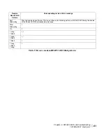
Page 73: ...easier to find out what the status of the DW4020 is via the interface than the LED status blinking The blink patterns are described below for your information Transmit READYLED Pattern Corresponding transmit status messages Off 4 or powered off On 8 2 Long 1 Short 1 2 Long 2 Short 2 2 Long 3 Short 11 1 Long 1 Short 3 1 Short 5 2 Short 10 13 14 15 16 21 22 23 3 Short 6 7 4 Short 12 17 Slow Alternat...

Page 74: ...atus message Fast Alternating Prior to downloading software This is a continuous fast blinking pattern with the RX LED being the inverse of the Ready LED No corresponding message Slow Alternating 1 On 5 1 Long 1 Short 3 6 1 Long 2 Short 4 7 1 Short 0 1 Long 1 Short 1 Long 2 Table 9 Receive modem READY LED blink patterns ...

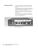
Page 75: ... DW4020 and a 100baseT Ethernet device is connected to the corresponding Ethernet port Otherwise the green LED will be off If the power is on and the light is off while a network device is connected then the device is a 10baseT device and the port is autosensing The yellow LED will also be on when power is applied to the DW4020 It will flash momentarily when there is LAN activity on the correspond...

Page 76: ...terminal connected to an asynchronous serial port Host In packet and message switching communications networks the collection of hardware and software that makes use of packet or message switching to support user to user i e end to end communications interprocess communications and distributed data processing More simply any computer that has full two way access to other computers on the Internet ...

Page 77: ...ed with the Network Information Centre NIC Computers on private TCP IP LANs however do not need public addresses since they do not need to be accessed by the public For this reason the NIC has reserved certain addresses that will never be registered publicly These are known as private IP addresses Receive modem downloads data from the satellite Also known as indoor receive unit IRU Router a device...

Page 78: ...d satellite link from the Internet allowing users to download information at a very high rate Turbo Internet services provide asymmetric connections between a customer PC and the Internet This enables users to download very large files at a very high rate of speed ...

Page 79: ... Glossary 66 1031484 0001 Revision 2 ...

Page 80: ...IP Internet protocol IRU indoor receive unit ISP Internet service provider ITU indoor transmit unit LAN local area network NAT network address translation NMC network management center NOC network operations center OPI outdoor pointing interface PEP performance enhancing proxy RX receive SDL software download TCP transmission control protocol TCP IP transmission control protocol Internet protocol ...

Page 81: ... Abbreviations and Acronyms 68 1031484 0001 Revision 2 ...

Page 82: ...int without doing any rounding and use the chart below to translate these two digits into the number of minutes 3 Enter the minutes number into the VSAT Longitude in minutes field in the Configure Boot Parameters screen 4 Repeat steps 1 2 and 3 for the VSAT Latitude in degrees and VSAT Latitude in minutes fields For example if the site s coordinates are Longitude 77 2395 deg West Latitude 38 8351 ...

Page 83: ...7 46 08 5 43 26 78 47 09 5 44 26 79 47 10 6 45 27 80 48 11 7 46 28 81 49 12 7 47 28 82 49 13 8 48 29 83 50 14 8 49 29 84 50 15 9 50 30 85 51 16 10 51 31 86 52 17 10 52 31 87 52 18 11 53 32 88 53 19 11 54 32 89 53 20 12 55 33 90 54 21 13 56 34 91 55 22 13 57 34 92 55 23 14 58 35 93 56 24 14 59 35 94 56 25 15 60 36 95 57 26 16 61 37 96 58 27 16 62 37 97 58 28 17 63 38 98 59 29 17 64 38 99 59 30 18 6...

Page 84: ...throughput across the satellite link Turbo Intranet involves using local devices to answer TCP overhead messages in the place of distant devices These devices efficiently send outroute data over the spacelink and buffer the data for transfer to local hosts within Table 10 The Internet Protocol IP is the basis for other protocol layers FTP File Transfer Protocol IP multicast Reliable method for del...

Page 85: ... number that identifies it and its network Actually the IP address is assigned to the connection rather than to the computer itself However it is assumed that the computers are not moved from their respective connections By convention these IP addresses are written by converting each byte 8 bits into a decimal number 0 to 255 and separating each byte by a period as in 192 77 43 4 This format calle...

Page 86: ... department A very large entity might require a class A network that would allow over 16 million individual IP address assignments Table 11 gives the ranges of IP addresses IANA reserves for specific purposes HNS customers have already acquired IP address ranges and supply these as needed to HNS installers Note however that many organizations of various sizes now use private IP addressing see Priv...

Page 87: ...nambiguous within an enterprise but may be ambiguous between enterprises Category 3 hosts that need network layer access outside the enterprise provided via IP connectivity hosts in the last category require IP addresses that are globally unambiguous Hosts in categories 1 and 2 are private hosts Hosts in Category 3 are public hosts Hosts in categories 1 and 2 do not need to be directly accessible ...

Page 88: ...so without any coordination with IANA or an Internet registry The address space can thus be used by many enterprises Addresses within this private address space will only be unique within the enterprise or the set of enterprises which choose to cooperate over this space so they may communicate with each other in their own private internet An enterprise that requests IP addresses for its external c...

Page 89: ...ters on the same LAN from computers in other departments or elsewhere in the world Computers on the same LAN can send messages directly to each other Messages for other LANs and the rest of the world need to be sent through a router In a scheme where the first three bytes identify the LAN network the subnet mask is 255 255 255 0 The decimal number 255 corresponds to the binary number 11111111 In I...

Page 90: ...em installation kit or inside the antenna box You must provide a 9 pin female female F F null modem serial cable The serial cable is used to configure the DW4020 via the serial port You will also need the installation specification or work order This is provided to you by HNS Figure 53 Items required for installation Read this manual and obtain serial cable and installation work order These items ...

Page 91: ... unit s performance may suffer if the wrong power supply is used This unit must be used with the power supply PN 1031105 0001 When power needs to be removed from the receive modem ALWAYS unplug the AC power cord from either the wall outlet surge protector or power strip NEVER pull the power cord from the back of the receive modem Doing so could damage the pins and also cause a short in the system ...

Page 92: ...igure 56 5 Double check that the components are installed in this order from top to bottom receive modem transmit modem Gateway see Figure 57 CAUTION The components must be stacked in this order Gateway on bottom transmit modem on top of Gateway receive modem on top of transmit modem See Figure 57 If the components are not stacked in the proper order the receive modem may overheat and malfunction ...

Page 93: ...Appendix C Installing the DW4020 Manually 80 1031484 0001 Revision 2 Figure 55 Mount the components on two clips Figure 56 Attach the other clips ...

Page 94: ...Appendix C Installing the DW4020 Manually 1031484 0001 Revision 2 81 Figure 57 Component stack Receive modem Transmit modem Gateway ...

Page 95: ...r supply adapter cable provides power to the Gateway and receive modem see Figure 58 7 Connect the receive coaxial cable to the receive modem and the transmit coaxial cable to the transmit modem see Figure 59 Figure 58 Attach interconnection cables Figure 59 Attach coaxial cables Transmit modem Ethernet card Receive modem Gateway USB cable Power supply adapter 25 pin connector cable Transmit modem...

Page 96: ...to connect to other computers via an Ethernet connection Reference UL 60950 Annex NAA Subclause reference 6 page 322 9 Attach the power supply cords to the power supply and to the power supply adapter Ensure that the power cord is tightly connected to the power supply modem and Gateway see Figure 61 The final assembly is shown in Figure 62 Figure 60 Attach network cables Transmit modem Ethernet ca...

Page 97: ...ng the DW4020 Manually 84 1031484 0001 Revision 2 Figure 61 Connect power cord Figure 62 Final assembly Transmit modem Ethernet card Receive modem Gateway T0091013 AC power cord DC power cord Power supply Ethernet cables ...

Page 98: ...leted Additional status information is available via the User Interface See Chapter 3 The User Interface on page 33 and the LEDs on the receive and transmit modems see Communicating with the Gateway through the serial port on page 95 Note In countries outside North America the DW4020 may be plugged with a physical adapter directly into a 220 V outlet Different countries may have different standard...

Page 99: ...4020 is power cycled However that blinking does not indicate anything about their status The DW4020 is extremely reliable If you find you cannot surf the Internet or the DW4020 seems to have a problem follow this sequence of steps below to identify and fix the problem Check whether the DW4020 LEDs or on or off The LEDs may indicate that a connection has become loose Reconnecting a cable or power c...

Page 100: ...s a STATUS and READY LED Note Whenever the LEDs do not function properly as described below check to be sure you have the correct power supply PN 1031105 0001 DW4020 LEDs status This section describes the LEDs appearance during typical DW4020 operation It also describes their appearance when some basic problem is occurring Normal operation no transmit or receive When the DW4020 is powered on but n...

Page 101: ...e protector See Figure 66 If the power cord was loose the receive modem READY led will come on when power is restored If securing the power cord does not solve the problem check all cable connections Tighten any that seem loose If the Receive modem READY LED still does not come on power cycle the DW4020 by unplugging the power cord from the wall outlet or surge protector waiting ten seconds and pl...

Page 102: ...ive modem READY LED not lit Figure 66 DW4020 power and cable connections Receive modem READY LED not lit Note that in many cases other modem LEDs will not be lit either Transmit modem Ethernet card Receive modem Gateway T0091013 AC power cord DC power cord Power supply Ethernet cables ...

Page 103: ...curely attached to the receive modem and plugged into the wall outlet or surge protector See Figure 66 If the power cord was loose the transmit modem READY led may come on If securing the power cord does not solve the problem check all cable connections Tighten any that seem loose If the transmit modem READY LED still does not come on power cycle the DW4020 by unplugging the power cord from the wa...

Page 104: ... or surge protector See Figure 66 If the power cord was loose the Gateway and receive modem READY LEDs will come on when power is restored If securing the power cord does not solve the problem check all cable connections Tighten any that seem loose If the Gateway READY LED still does not come on power cycle the DW4020 by unplugging the power cord from the wall outlet or surge protector waiting ten...

Page 105: ...ghten any that seem loose If the Gateway STATUS LED still does not come on continuously power cycle the DW4020 by unplugging the power cord from the wall outlet or surge protector waiting ten seconds and plugging it back in If the problem persists contact technical support LED blinking indicating status codes The DW4020 modems READY LEDs can blink in various patterns These patterns correlate to th...

Page 106: ...Slow Alternating 9 18 19 20 Fast Alternating The ITU interface testing This is a continuous fast blinking pattern with the Transmit LED being the inverse of the Ready LED No corresponding message Receive READY LED Pattern Corresponding receive status message Fast Alternating Prior to downloading software This is a continuous fast blinking pattern with the RX LED being the inverse of the Ready LED ...

Page 107: ... DW4020 and a 100baseT Ethernet device is connected to the corresponding Ethernet port Otherwise the green LED will be off if the power is on and the light is off while a network device is connected then the device is a 10baseT device and the port is autosensing The yellow LED will also be on when power is applied to the DW4020 It will flash momentarily when there is LAN activity on the correspond...

Page 108: ...erminal emulation program to access the Gateway software Main Menu The first time you do this you configure the COM1 port s properties and save the connection as a Hyperterminal ht file For all subsequent installs you simply open the file Figure 71 Location of Gateway serial port Gateway serial port Note You can often find the Hyperterminal icon in the Accessories subfolder in the Windows Start me...

Page 109: ...ssories Hyperterminal and click on the Hyperterminal file see Figure 72 The Connection Description window appears see Figure 73 The red and yellow phones icon is highlighted in blue You will establish a new connection Figure 72 Starting Hyperterminal Figure 73 Connection Description window ...

Page 110: ...rom the Connect Using pull down list see Figure 74 Select COM2 is you want to use that port e Select OK The COM1 Parameters window appears f Configure the Port Settings by selecting the parameters below from the appropriate pull down list see Figure 75 Bits per second baud 9600 Data bits 8 Parity none Stop bits 1 Flow control none Figure 74 Connect To window ...

Page 111: ...ve As window appears i Enter DW4020 in the File name field and select Save The window disappears Now you will simply be able to select the DW4020 ht file when connecting the Gateway and the laptop during future installs j Select Call Connect The laptop will connect to the Gateway Figure 75 COM1 Properties window and pull down menus ...

Page 112: ...he Gateway and laptop Start Hyperterminal Select File Open DW4020 ht The Gateway and laptop will connect Main Menu a Configure Boot Parameters b Display Current Configuration c Display Satellite Interface Statistics d Display Active Routing Table f Run Software Download Monitor h Display Reset History i Installation t Run Final Built in Tests pc Parameter Clear Clear Configuration pw Parameter Wri...

Page 113: ...r Z to return to the Main Menu Figure 78 Satellite Interface Statistics menu with Display Satellite Interface Serial Number displayed CAUTION You must confirm the receive modem electronic serial number through the serial connection using Hyperterminal when configuring the DW4020 If the electronic serial number is different from the barcode receive modem serial number call the installer hotline for...

Page 114: ...inutes values 1 Enter a at the Main Menu prompt Each parameter shown in Figure 80 appears one at a time one line at a time For example the first parameter to appear after you enter a is the VSAT Return Path Parameter as shown in Figure 79 All the parameters are shown in the Display Current Configuration screen in Figure 80 The screen is displayed by entering b at the Main Menu prompt Note Two good...

Page 115: ...de in minutes 10 10 VSAT Longitude Hemisphere West West VSAT Latitude in degrees 39 39 VSAT Latitude in minutes 10 10 VSAT Latitude Hemisphere North North Satellite Channel Frequency 11100 x 100Khz 11100 x 100Khz Receive Symbol Rate 30000000 Sps 30000000 Sps LNB Polarization Vertical Vertical LNB 22KHz Switch On On Filter Rolloff 20 20 LAN1 IP Address 66 82 56 50 66 82 56 50 LAN1 Subnet Mask 255 2...

Page 116: ...ify the parameter values and match them to the installation or NOC specification The Installation Menu After you have entered the boot parameters use the Installation Menu to receive and transmit point the antenna Transmit pointing uses both an automatic and manual mode The Outdoor Pointing Interface OPI device can also be used to point an antenna used with a DW4020 Follow the instructions in the ...

Page 117: ...CP is not available Transmitter Automatic not available will appear in the menu CAUTION The two way satellite dish assembly emits radio frequency energy when in the transmit mode Unplug indoor power connection before performing maintenance or adding upgrades to any satellite dish components To avoid risk of injury do not place head or other body parts between feed horn and reflector when system is...

Page 118: ... 30 The receive modem is locked onto a satellite signal but is waiting for a message confirming that it is locked to the correct signal An unchangeable value of 30 indicates that the receive modem is locked onto a wrong signal 3 If the SQF is less than 30 refine the antenna pointing to bring the SQF over 40 and to as close to 99 as possible The SQF message updates automatically There is a delay of...

Page 119: ...tomatic Automatic cross polarization ACP is used for a rapid Pass Fail test of the antenna s transmit polarization adjustment If you pass ACP the unit is enabled and no further antenna pointing is needed 1 Enter B at the Installation Menu prompt The Antenna Pointing Transmitter Automatic screen appears Otherwise the screen shows your current queue position until the test can be run Sometimes a num...

Page 120: ... learn if ranging is available and being used by the unit enter d If it is available and used SUCESSFUL will appear if not NEED RANGING will appear Ranging must be done before you exit the Installation Menu CAUTION Any time you enter the DW4020 Installation Menu the transmitter is turned off for safety reasons Do not enter I to access the Installation Menu after this point unless instructed to do ...

Page 121: ...nnect with the hub server 3 If SDL does not progress beyond this message check the following The SDL control channel s multicast IP address Return to the Main Menu Enter b to view the current configuration Check that the SDL Control Channel Multicast Address is correct If not enter the correct address The Ready lights to ensure they are on See The DW4020 LEDs on page 86 and Communicating with the ...

Page 122: ...e The new configuration takes effect 7 At the Main Menu prompt select f to monitor SDL progress The following messages are displayed The DW4020 may now be hooked up to either a configured PC or network Figure 84 Gateway reset SDL Initialization complete Awaiting first heartbeat msg Received first heartbeat message All files downloaded No pending changes ...

Page 123: ...tics In the display that appears see Figure 85 check if frames are being accepted The Frames Received and F error values indicate the DW4020 is detecting frames and correctly receiving and demodulating an outroute signal Note the Signal Quality Factor is also reported if the SQF is below 31 the antenna must be repointed The Receive Status and Transmit Status fields report whether the receive and t...

Page 124: ...000000 0000000000 0000000000 0000000000 0000000000 02000A0B36E3 0000000171 0000000000 0000000000 0000000000 01005E6EEFEF 0000000012 0000000000 0000000000 0000000000 030001000009 0000007651 0000000000 0000000000 0000000000 030001020000 0000000476 0000000000 0000000000 0000000000 030001010000 0000001419 0000000000 0000000000 0000000000 Figure 86 Display Traffic Statistics screen TCP Spoofing Flag Di...

Page 125: ... only Note that you reset the DW4020 by typing rr at the Main Menu prompt and pressing Enter You can force the DW4020 to download new software keys by typing rd and pressing Enter Reading factory information Option g displays read only information from the manufacturer This option automatically returns to the Final Test menu Final Test Menu a LED Test Pattern b Ethernet Ports Test c Modem Signal T...

Page 126: ... from the factory with Dynamic Host Configuration Protocol DHCP enabled Therefore your installer laptop PC must have DHCP enabled and set to automatically obtain IP addresses Windows 98SE and ME 1 On the client computer go to Start Settings Control Panel and double click Network See Figure 91 Note On Windows ME computers choose View All Control Panel Options to see the Network icon 2 A list of net...

Page 127: ...erties The TCP IP Properties window appears See Figure 93 4 In the IP Address tab select Obtain an IP address automatically 5 Select the Gateway tab Remove any installed gateways by selecting them and selecting Remove See Figure 94 6 Select the Disable DNS radio button on the DNS Configuration tab 7 Select OK to accept the updates for the TCP IP properties Figure 92 Network window ...

Page 128: ...84 0001 Revision 2 a 115 8 Select OK to close the list of network components Windows may request the installation CD ROM to complete updating the TCP IP settings 9 Restart the computer if it does not do so automatically Figure 93 TCP IP Properties Figure 94 Gateway tab ...

Page 129: ...ust be listed If it is not the network is not installed correctly 3 Right click the Local Area Connection icon that represents the network adapter that connects the computer to the DW4020 and select Properties The Local Area Connections Properties window appears See Figure 96 4 Ensure that the Client for Microsoft Networks and Internet Protocol TCP IP are installed and checked If NetBEUI is instal...

Page 130: ...l Properties window appears See Figure 97 7 Ensure that both Obtain an IP Address Automatically and Obtain DNS Server Address Automatically are selected If not select them 8 Select OK to close the open dialog boxes and finish the configuration 9 Restart the computer even if Windows does not require you to do so This will ensure that the network settings are automatically reset Figure 97 Internet P...

Page 131: ...lect Properties Note If the Local Area Connection icon appears with a red X then check your connections The red X must not be present in order for you to be successful 4 Ensure that the Client for Microsoft Networks and Internet Protocol TCP IP are installed and checked If NetBEUI is installed uninstall it See Figure 99 5 Select Internet Protocol TCP IP and select Properties See Figure 100 Note Be...

Page 132: ...Appendix D Configuring the installer laptop for IP addressing 1031484 0001 Revision 2 a 119 Figure 99 Local Area Connection Properties Figure 100 Internet Protocol Properties ...

Page 133: ...Appendix D Configuring the installer laptop for IP addressing 120 1031484 0001 Revision 2 a ...

Page 134: ...to establish operating parameters Register the end user and select subscription options via Websetup Record site ID Gateway IP address subnet mask and service offering on cover of User Guide Transfer of parameter information to Gateway Exit Websetup Assemble and install the satellite antenna Run cables from the outdoor components to the indoor equipment Clearly label the receive and transmit coaxi...

Page 135: ...Appendix E Installation checklist 122 1031484 0001 Revision 2 ...

Page 136: ...ateway LED 17 85 H hardware characteristics 2 heat dissipation 5 host 72 I Indoor Receive Unit IRU 1 Indoor Transmit Unit ITU 1 Installation checklist summary 121 Installation Menu 103 Internet Assigned Numbers Authority IANA 72 Internet Protocol 71 IP addressing 72 L local area network 2 M manual cross pol 28 modems LEDs 18 86 N null modem serial cable 11 77 P packet error probability PEP 111 par...

Page 137: ...em Information 45 T Task checklist 121 TCP spoofing 72 TCP IP internet protocol suite 71 The Home screen 35 transmission control protocol 71 Transmit modem 1 transmit modem 5 Transmit Status 37 Turbo Intranet 71 TxCode 53 U User Interface is accessed 34 V Verifying correct DW4020 operation 110 Verifying software download 108 W Websetup 22 ...

Reviews: