2112 Fenton Logistics Park Blvd
Fenton, Missouri 63026 USA
P/N KIL00921498 FORM NO. K1498 ECO-6-023-19 R04/19
Page 3 of 4
IMPORTANT NOTE:
Turn off electricity to circuit at main fuse or at circuit breaker.
1. For NEC installation connection to the black (Line), white (Neutral) and green (Ground/Earth) can be made with
appropriate wire connectors outside of the fixture, the connectors can be placed in the fixture through the hub. If the
terminal blocks are going to be used, remove the housing cover.
2. If terminal blocks are used, discard the wires on the entry side of the terminal block. Run supply wire to fixture
through applicable hub. Make watertight joint using sealing fittings at appropriate hole. The hub in the endcap is for ¾
”-
14NPT (or 2 x M20 may be ordered).
3. Pull the supply wires into housing through the conduit hub and connect the appropriate leads using insulated wire
nuts or use the terminal blocks present. See below for wiring battery backup fixtures.
4. Replace the housing cover.
5. Turn on electricity to verify fixture is operating properly.
Battery Backup Fixtures:
IMPORTANT: To turn the fixture completely off, an un-switched AC power source of 120VAC to 277VAC is required for the
yellow/black and white leads. If the yellow/black and white leads are attached to switched power, the fixture will go into battery
backup mode if the switch is turned off.
IMPORTANT: A switched or un-switched AC power source of 120VAC to 277VAC is acceptable for the black lead. Fixtures with
terminal blocks are shipped with a jumper between the terminals of the black and yellow/black wire. Remove the wire link
(jumper) and attach the yellow black wire to line voltage when local switching is required.
The battery must be charged for at least 12 hours prior to testing.
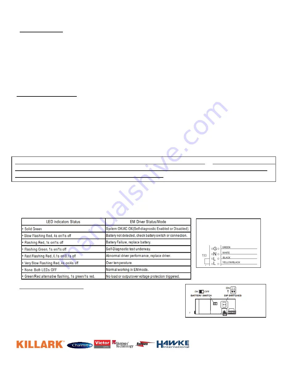
SELF DIAGNOSTIC INSTRUCTIONS / OPERATION: The self diagnostic feature is set from the factory. The
emergency LED driver will conduct a self check for thirty (30) minutes every thirty (30) days; and ninety (90) minutes
or one hundred eighty (180) minutes self check every 12 months. After every self check the LED indicator light will
indicate a status signal. To disable this feature set the Dip Switch 2 to the OFF Position. Dip Switch 1 in the ON
position will power the fixture in battery backup mode at 10W for a minimum of 30 minutes. Dip Switch 1 in the OFF
position will power the fixture in battery backup mode at 5W for a minimum of 60 minutes.
Battery Changing Procedure:
1. Remove the housing cover.
2. Slide the gear tray out of the housing until the emergency driver is
exposed. Remove wires from lever nuts as necessary. To remove a wire
from a lever nut, fully push up the lever and remove the conductor.
3. Remove the two screws that hold the driver to the gear tray.
4. Remove the two screws that hold the battery compartment cover to the driver.
5. Disconnect the connector and replace the new battery.
6. Reassemble
The battery switch must be turned to the “ON” position for the fixture to operate correctly. The fixture will not light up in
battery backup mode until AC power is supplied once while the
battery switch is in the “ON” position. Thereafter, the
fixture will operate in battery backup mode when the AC power is off.
Battery Back-Up
Connection with
Terminal Block


