


Figure 3-26
Removing a filler panel (2)
Step 7
Take a spare riser card tray out of its ESD bag.
Step 8
Install PCIe cards on the riser card tray. For details, see
.
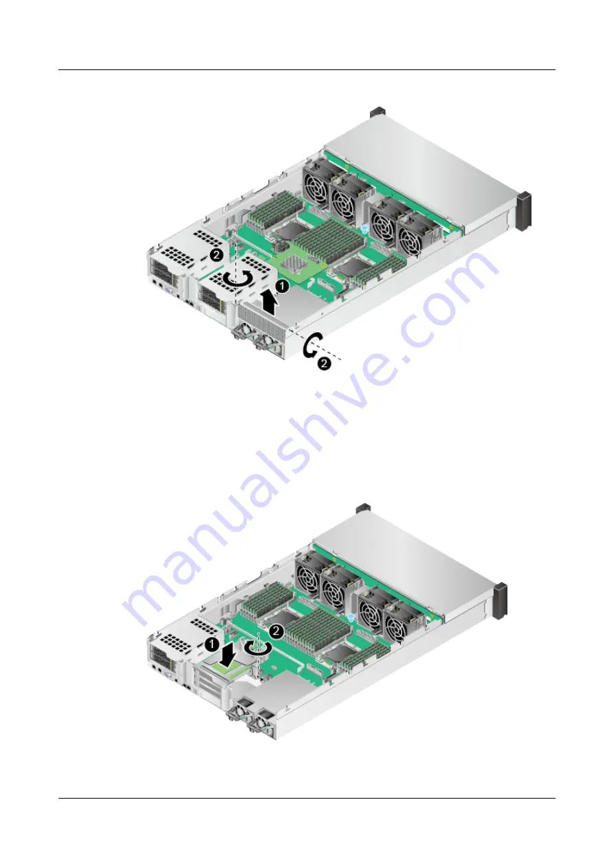
Step 9
Install the riser card tray and tighten the screw. See
Figure 3-27
Installing a riser card tray (1)
2288H V5 Server
User Guide
3 Basic Operations
Issue 04 (2018-09-04)
Copyright © Huawei Technologies Co., Ltd.
65


