background image

CA UTION

● Cables and terminals must match each other. For example, cables with a cross-

sectional area of 16 mm

2

 must be used with terminals whose nominal cross-

sectional area is 16 mm

2

, and terminals of other models are not allowed.

● To prevent short circuits, refer to the following tables for the specifications

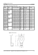
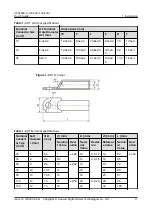
when selecting OT and DT terminals.

● When preparing cables, use OT or DT terminals that match the cable cross-

sectional areas to prevent copper core exposure, which may cause arcing

between cables and consequently result in safety risks.

Table 1-1 Recommended cross-sectional areas for power cables

Item

30

kVA

40 kVA 60 kVA

80

kVA

120 kVA

Mains

input

Mains input current

(A)

53

71

UPS5000-

A-60KTTL-H: 96
UPS5000-

A-60KTTL: 107

142

UPS5000-

A-120KTTL-H:

191
UPS5000-

A-120KTTL:

213

Recomme

nded

cross-

sectional

area

(mm

2

)

L1

4 x 10

4 x 16

4 x 35

4 x 50 4 x 95

L2

L3

N

Bypass

input

Bypass input current

(A)

46

61

91

122

182

Recomme

nded

cross-

sectional

area

(mm

2

)

L1

4 x 10

4 x 16

4 x 35

4 x 35 4 x 70

L2

L3

N

Output

Output current (A)

46

61

91

122

182

Recomme

nded

cross-

sectional

area

(mm

2

)

U

4 x 10

4 x 16

4 x 25

4 x 35 4 x 70

V

W

UPS5000-A-(30 kVA–120 kVA)

Quick Guide

1 Installation

Issue 14 (2022-09-06) Copyright © Huawei Digital Power Technologies Co., Ltd.

7

Summary of Contents for UPS5000-A-120 kVA

Page 1: ...UPS5000 A 30 kVA 120 kVA Quick Guide Issue 14 Date 2022 09 06 HUAWEI DIGITAL POWER TECHNOLOGIES CO LTD ...

Page 2: ... features described in this document may not be within the purchase scope or the usage scope Unless otherwise specified in the contract all statements information and recommendations in this document are provided AS IS without warranties guarantees or representations of any kind either express or implied The information in this document is subject to change without notice Every effort has been mad...

Page 3: ...high level of risk which if not avoided will result in death or serious injury Indicates a hazard with a medium level of risk which if not avoided could result in death or serious injury Indicates a hazard with a low level of risk which if not avoided could result in minor or moderate injury Indicates a potentially hazardous situation which if not avoided could result in equipment damage data loss...

Page 4: ...018 04 18 Updated the model specifications 09 2018 01 03 Updated the output electrical specifications and typical configurations Updated the software version 08 2017 06 09 Updated the software version 07 2016 12 03 Updated the space reserved in front of the cabinet in section Site Planning Added section UPS Cable Connection Reference Added checking for foreign matters in section Verifying the Inst...

Page 5: ... UPS5000 A 60 kVA 80 kVA 120 kVA Updated chapter Troubleshooting 02 2013 11 18 Added figures of OT and DT terminals for the UPS5000 A and tables that list their specifications 01 2013 11 05 This issue is the first official release UPS5000 A 30 kVA 120 kVA Quick Guide About This Document Issue 14 2022 09 06 Copyright Huawei Digital Power Technologies Co Ltd iv ...

Page 6: ...1 3 1 Installing the Chassis 33 1 3 2 Installing Antiseismic Kits 43 1 3 3 UPS Cable Connection Reference 44 1 3 4 Installing Cables 45 1 3 5 Connecting a Remote EPO Switch 51 1 4 Installing a Parallel System 51 1 5 Verifying the Installation 55 2 Single UPS Commissioning 60 2 1 Powering On and Starting the UPS 60 2 1 1 Power On 60 2 1 2 Initial Startup 60 2 1 3 Starting the Inverter 62 2 1 4 Powe...

Page 7: ...Starting a Parallel System 67 3 2 Shutting Down and Powering Off a Parallel System 72 UPS5000 A 30 kVA 120 kVA Quick Guide Contents Issue 14 2022 09 06 Copyright Huawei Digital Power Technologies Co Ltd vi ...

Page 8: ...rating temperatures higher than 30 C shorten the battery lifespan and operating temperatures lower than 20 C reduce the battery backup time Clearances Reserve sufficient clearances around the cabinet to facilitate operations and ventilation Reserve a clearance of at least 800 mm from the front of the cabinets for ventilation and operations Reserve a clearance of at least 300 mm from the top of the...

Page 9: ...based on the site requirements Personal protective equipment Safety helmet Goggles Protective shoes Reflective vest ESD gloves Insulated gloves Protective gloves Safety harness UPS5000 A 30 kVA 120 kVA Quick Guide 1 Installation Issue 14 2022 09 06 Copyright Huawei Digital Power Technologies Co Ltd 2 ...

Page 10: ...screwdriver M2 5 Phillips insulated torque screwdriver M4 M5 M6 Insulated torque socket wrench Including extended sockets M8 M10 M12 M16 Hex key Adjustable torque wrench Hammer drill Hammer drill bit Φ16 mm Claw hammer UPS5000 A 30 kVA 120 kVA Quick Guide 1 Installation Issue 14 2022 09 06 Copyright Huawei Digital Power Technologies Co Ltd 3 ...

Page 11: ...tter Wire stripper Diagonal pliers RJ45 crimping tool Electro hydraulic pliers Cord end terminal crimping tool Heat gun Measurement instruments Height gauge Laser locator Electroprobe Thermometer UPS5000 A 30 kVA 120 kVA Quick Guide 1 Installation Issue 14 2022 09 06 Copyright Huawei Digital Power Technologies Co Ltd 4 ...

Page 12: ...ester Phase sequence meter Dielectric strength tester Machinery Small cutter Cable reel Insulation megohmmeter Engineering auxiliary materials Label Cable tie Cotton cloth Sandpaper UPS5000 A 30 kVA 120 kVA Quick Guide 1 Installation Issue 14 2022 09 06 Copyright Huawei Digital Power Technologies Co Ltd 5 ...

Page 13: ...m cleaner Flashlight Hole saw 1 1 3 Preparing Power Cables NOTICE If multiple UPSs are connected in parallel input and output power cables for each UPS should have the same length and specifications UPS5000 A 30 kVA 120 kVA Quick Guide 1 Installation Issue 14 2022 09 06 Copyright Huawei Digital Power Technologies Co Ltd 6 ...

Page 14: ...ult in safety risks Table 1 1 Recommended cross sectional areas for power cables Item 30 kVA 40 kVA 60 kVA 80 kVA 120 kVA Mains input Mains input current A 53 71 UPS5000 A 60KTTL H 96 UPS5000 A 60KTTL 107 142 UPS5000 A 120KTTL H 191 UPS5000 A 120KTTL 213 Recomme nded cross sectional area mm2 L1 4 x 10 4 x 16 4 x 35 4 x 50 4 x 95 L2 L3 N Bypass input Bypass input current A 46 61 91 122 182 Recomme ...

Page 15: ... UPS5000 A 120KTTL 329 Battery maximum discharge current A 98 131 UPS5000 A 60KTTL H 142 UPS5000 A 60KTTL 197 262 UPS5000 A 120KTTL H 284 UPS5000 A 120KTTL 394 Recomme nded cross sectional area mm2 3 x 16 3 x 35 3 x 70 3 x 95 3 x 150 N Ground cable Recomme nded cross sectional area mm2 PE 1 x 10 1 x 16 1 x 16 1 x 25 1 x 50 UPS5000 A 30 kVA 120 kVA Quick Guide 1 Installation Issue 14 2022 09 06 Cop...

Page 16: ... The AC voltage loss is less than 3 and the DC voltage loss is less than 1 The recommended cross sectional areas in the table meet the basic through current requirements Users should evaluate the line voltage loss based on the actual cable length If the voltage loss exceeds the requirements increase the cable cross sectional areas properly Copper cables whose conductor supports the maximum operati...

Page 17: ...kVA Crimped DT terminal M10 11 mm 27 N m 30 40 kVA Battery input Crimped OT terminal M8 9 mm 13 N m 60 80 kVA Crimped DT terminal M10 11 mm 27 N m 120 kVA Crimped DT terminal M12 13 mm 47 N m 30 40 kVA Output Crimped OT terminal M6 6 5 mm 4 5 N m 60 80 kVA Crimped DT terminal M8 9 mm 13 N m 120 kVA Crimped DT terminal M10 11 mm 27 N m 30 40 kVA PE Crimped OT terminal M6 6 5 mm 4 5 N m 60 120 kVA C...

Page 18: ...able 1 4 DT terminal specifications Nominal Connect or Size mm2 Bolt Diamete r mm ΦH mm d mm D mm W mm L mm Nomina l Value Devi ation Nomi nal Value Deviat ion Referenc e Value Nomin al Value Devi ation 25 6 6 5 7 0 30 10 0 0 12 14 60 1 50 35 8 8 4 8 5 12 0 0 16 16 66 50 8 8 4 10 0 40 14 19 72 70 10 10 5 12 16 22 80 95 10 10 5 13 18 25 87 120 12 13 15 0 50 20 0 0 24 28 96 150 12 13 16 22 32 103 UP...

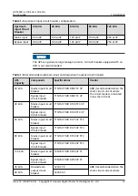
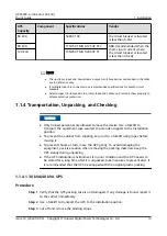
Page 19: ... circuit breaker is located is less than 36 kA Bypass input circuit breaker T1N160 TMD R80 FFC 3P 40 kVA Mains input circuit breaker T1N160 TMD R100 FFC 3P Bypass input circuit breaker T1N160 TMD R100 FFC 3P 60 kVA Mains input circuit breaker T1N160 TMD R125 3P FFC Bypass input circuit breaker T1N160 TMD R125 3P FFC 80 kVA Mains input circuit breaker T1N160 TMD R160 3P FFC Bypass input circuit bre...

Page 20: ...se secured to a wooden support to the installation position To prevent the cabinet from toppling secure it to a forklift using ropes before moving it To prevent shocks or falls move the UPS gently To avoid damaging the equipment exercise caution when removing the packing materials Keep the UPS steady during unpacking If the UPS installation environment is in poor condition and the UPS needs to be ...

Page 21: ...ice is intact 1 Visually inspect the UPS appearance for shipping damage If any damage is found notify the carrier immediately 2 Check that the fittings comply with the packing list If there is any discrepancy keep a record and contact the supplier immediately UPS5000 A 30 kVA 120 kVA Quick Guide 1 Installation Issue 14 2022 09 06 Copyright Huawei Digital Power Technologies Co Ltd 14 ...

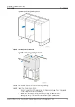
Page 22: ...ier immediately Step 2 Use a forklift to transport the UPS to the installation position Step 3 Hold the sliding plate steady Cut and remove the binding straps Put down the sliding plate gently Figure 1 6 Removing binding straps Step 4 Remove the packing materials and foam UPS5000 A 30 kVA 120 kVA Quick Guide 1 Installation Issue 14 2022 09 06 Copyright Huawei Digital Power Technologies Co Ltd 15 ...

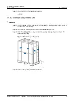
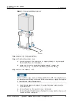
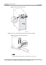
Page 23: ...panel NOTICE Remove both the upper and lower front panels from the UPS Removing the lower one facilitates the removal of L shaped brackets Removing the upper one prevents it from falling off during transportation 1 Press the switches on both sides of the upper front panel and remove the upper front panel 2 Remove the screws that secure the lower front panel 3 Remove the ground cable between the lo...

Page 24: ...t secure the chassis and pallet Figure 1 9 Removing the L shaped brackets NOTE Store the removed L shaped brackets which will be used to secure the UPS UPS5000 A 30 kVA 120 kVA Quick Guide 1 Installation Issue 14 2022 09 06 Copyright Huawei Digital Power Technologies Co Ltd 17 ...

Page 25: ...ble support bases When you assemble two modules align the connecting buckle with the hole Figure 1 10 Assembling support bases Step 2 Pull out the rear handle from the device 1 Loosen the screws on the back end handle anticlockwise 2 Pull the handle out of the groove UPS5000 A 30 kVA 120 kVA Quick Guide 1 Installation Issue 14 2022 09 06 Copyright Huawei Digital Power Technologies Co Ltd 18 ...

Page 26: ...s require two support bases and the distance between support bases must be greater than 480 mm Figure 1 12 Placing the UPS on the support bases unit mm Step 4 Push the rear handle into the groove For details see the instructions on the chassis UPS5000 A 30 kVA 120 kVA Quick Guide 1 Installation Issue 14 2022 09 06 Copyright Huawei Digital Power Technologies Co Ltd 19 ...

Page 27: ... 1 Insert the lower end of the panel into the UPS 2 Gently close the upper end of the panel Figure 1 14 Installing the front panel Step 6 To prevent misoperations you are advised to install a lock diameter of the effective lock cylinder 5 6 3 mm for the maintenance bypass switch UPS5000 A 30 kVA 120 kVA Quick Guide 1 Installation Issue 14 2022 09 06 Copyright Huawei Digital Power Technologies Co L...

Page 28: ...left and right side panels 3 Remove the handles 4 Remove the front panel MDU and cables from the chassis Figure 1 16 Removing the left and right side panels handles and MDU from the chassis Step 2 Flip the ready switches on the power unit and bypass unit to not ready Remove the screws from the mounting ears of the bypass unit and remove the power unit and bypass unit UPS5000 A 30 kVA 120 kVA Quick...

Page 29: ...U on the rack 1 Align the lower edge of the guide rail with the lower edge of a U scale and then engage the mounting ears on both ends of the guide rail into the mounting holes NOTICE Ensure that the lower edge of the guide rail is aligned with the lower edge of a U scale UPS5000 A 30 kVA 120 kVA Quick Guide 1 Installation Issue 14 2022 09 06 Copyright Huawei Digital Power Technologies Co Ltd 22 ...

Page 30: ...crewdriver Figure 1 19 Floating nut installation positions Figure 1 20 Installing a floating nut 3 Secure the back end of the guide rail using panel screws Do not secure the front end of the guide rail Install the other guide rail in the same method UPS5000 A 30 kVA 120 kVA Quick Guide 1 Installation Issue 14 2022 09 06 Copyright Huawei Digital Power Technologies Co Ltd 23 ...

Page 31: ... and secure the front end of the guide rail using panel screws Figure 1 22 Position of the subrack Step 5 Replace the mounting ears on the left and right sides of the power unit UPS5000 A 30 kVA 120 kVA Quick Guide 1 Installation Issue 14 2022 09 06 Copyright Huawei Digital Power Technologies Co Ltd 24 ...

Page 32: ...ypass unit and flip all ready switches to ready Figure 1 24 Reinstalling the power unit and bypass unit Step 7 Rotate the removed MDU 90 degrees clockwise install it with the support and connect cables UPS5000 A 30 kVA 120 kVA Quick Guide 1 Installation Issue 14 2022 09 06 Copyright Huawei Digital Power Technologies Co Ltd 25 ...

Page 33: ...ront panel 90 degrees clockwise Figure 1 26 Installing the front panel Step 9 Recommended Install a lock for the maintenance bypass switch as shown in Figure 1 15 End UPS5000 A 30 kVA 120 kVA Quick Guide 1 Installation Issue 14 2022 09 06 Copyright Huawei Digital Power Technologies Co Ltd 26 ...

Page 34: ...te a cable into the cabinet and bind it to a nearby beam Step 2 Pull the cable to the copper bar to which the cable is to be connected determine the cable length and mark the cable at the position where the cable is to be cut Step 3 Pull the marked cable out of the cabinet cut the cable from the marked position strip the cable and crimp a terminal Figure 1 27 Preparing a cable terminal outside the...

Page 35: ...ted installation mode is used as an example to describe how to install cables The number and colors of cables in the following figures are for reference only Procedure Step 1 Remove the terminal block cover Figure 1 29 Removing the cover Step 2 Install ground cables UPS5000 A 30 kVA 120 kVA Quick Guide 1 Installation Issue 14 2022 09 06 Copyright Huawei Digital Power Technologies Co Ltd 28 ...

Page 36: ...otective ground label Step 3 Install UPS output power cables Figure 1 31 Connecting output power cables Step 4 Install AC input power cables One power source UPS5000 A 30 kVA 120 kVA Quick Guide 1 Installation Issue 14 2022 09 06 Copyright Huawei Digital Power Technologies Co Ltd 29 ...

Page 37: ...ources a Remove the copper bars connecting mains and bypass inputs Figure 1 33 Removing copper bars b Install AC input power cables UPS5000 A 30 kVA 120 kVA Quick Guide 1 Installation Issue 14 2022 09 06 Copyright Huawei Digital Power Technologies Co Ltd 30 ...

Page 38: ... the positive and negative battery strings Take a battery string consisting of 40 batteries for example The battery neutral wire is routed from the middle of positive and negative battery strings each consisting of 20 batteries UPS5000 A 30 kVA 120 kVA Quick Guide 1 Installation Issue 14 2022 09 06 Copyright Huawei Digital Power Technologies Co Ltd 31 ...

Page 39: ... on the monitoring interface card 2 If the UPS needs to connect to an external network management device connect the external network management device to the RS485 port on the monitoring interface card Figure 1 37 Cable route 1 Communications cable route End UPS5000 A 30 kVA 120 kVA Quick Guide 1 Installation Issue 14 2022 09 06 Copyright Huawei Digital Power Technologies Co Ltd 32 ...

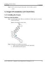
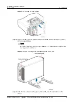
Page 40: ...ut switch when you trigger EPO Connect the EPO switch to the specified dry contact on the UPS using a cable NOTE By default the EPO switch is off When it is turned on EPO is triggered Figure 1 38 Cable connection for an NO EPO switch 1 3 Single UPS Installation 60 kVA 80 kVA 120 kVA 1 3 1 Installing the Chassis Tower mounted Installation Non secured Installation Step 1 Lower the four leveling feet...

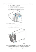
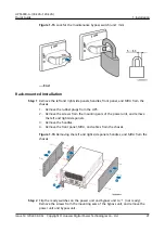
Page 41: ... the upper front panel Step 5 To prevent misoperations you are advised to install a lock diameter of the effective lock cylinder 5 10 mm for the maintenance bypass switch Figure 1 40 Lock for the maintenance bypass switch End Tower mounted Installation Secured Installation Step 1 Determine the position for installing the UPS and mark mounting holes UPS5000 A 30 kVA 120 kVA Quick Guide 1 Installati...

Page 42: ...ole depth ranges from 52 mm to 60 mm 2 Slightly tighten the expansion bolt and vertically insert it into the hole Knock the expansion bolt using a rubber mallet until the expansion sleeve is fully inserted into the hole 3 Partially tighten the expansion bolt 4 Remove the bolt spring washer and flat washer NOTICE Knock the expansion bolt into the hole until the expansion sleeve completely fits into...

Page 43: ... to the chassis and secure the chassis to the floor 1 Secure the two L shaped brackets to the front and rear of the chassis 2 Adjust the chassis to ensure that the expansion bolts align with the four half holes beneath 3 Check the chassis levelness using a level If the chassis is not leveled adjust the leveling feet 4 Secure the two L shaped brackets to the floor Figure 1 43 Installing L shaped br...

Page 44: ...rt of the rack for bottom cable routing Step 1 Install guide rails total height 2 U on the left and right sides at the lowest part of the rack NOTICE The UPS is heavy and cables are routed in from the bottom You are advised to install the UPS at the lowest part of the rack 1 Level the bottom plane of a guide rail with the lower edge of U scale 01 and engage the mounting ears on both ends of the gu...

Page 45: ...screws This facilitates subsequent adjusting when installing reinforced beams Figure 1 45 Securing a guide rail front view Step 2 Install a stiffening beam at the front and rear of the rack respectively After the installation is complete tighten the panel screws that secure the guide rails UPS5000 A 30 kVA 120 kVA Quick Guide 1 Installation Issue 14 2022 09 06 Copyright Huawei Digital Power Techno...

Page 46: ...front of the rack and install floating nuts NOTICE Level the Bottom line on the scale plate with the lower edge of U sale 01 on the rack Install floating nuts onto the mounting holes for the mounting bar that corresponds to Hole location lines UPS5000 A 30 kVA 120 kVA Quick Guide 1 Installation Issue 14 2022 09 06 Copyright Huawei Digital Power Technologies Co Ltd 39 ...

Page 47: ...ng a floating nut Step 4 Flip the ready switches on the power units to not ready and remove the power units NOTICE Two persons are required to move a power unit Keep the power unit horizontal during movement UPS5000 A 30 kVA 120 kVA Quick Guide 1 Installation Issue 14 2022 09 06 Copyright Huawei Digital Power Technologies Co Ltd 40 ...

Page 48: ... rack Figure 1 50 Installing mounting ears Step 6 Adjust the four leveling feet using an adjustable wrench until the bottom of the UPS is level with the Edge of cabinet line on the scale plate and level the UPS chassis UPS5000 A 30 kVA 120 kVA Quick Guide 1 Installation Issue 14 2022 09 06 Copyright Huawei Digital Power Technologies Co Ltd 41 ...

Page 49: ...y switches to ready Step 9 Reinstall the ground cable between the lower front panel and the UPS chassis and reinstall the lower front panel Step 10 Reinstall the upper front panel Step 11 Recommended Install a lock for the maintenance bypass switch as shown in Figure 1 40 End UPS5000 A 30 kVA 120 kVA Quick Guide 1 Installation Issue 14 2022 09 06 Copyright Huawei Digital Power Technologies Co Ltd ...

Page 50: ... them to the floor 1 Install antiseismic kits to the front and rear of the chassis 2 Adjust the chassis position so that the expansion bolt holes are aligned with the four holes at the bottom of the chassis 3 Check the chassis levelness using a level If the chassis is not leveled adjust the leveling feet 4 Secure the front and rear antiseismic kits to the floor Figure 1 53 Securing antiseismic kit...

Page 51: ...te a cable into the cabinet and bind it to a nearby beam Step 2 Pull the cable to the copper bar to which the cable is to be connected determine the cable length and mark the cable at the position where the cable is to be cut Step 3 Pull the marked cable out of the cabinet cut the cable from the marked position strip the cable and crimp a terminal Figure 1 54 Preparing a cable terminal outside the...

Page 52: ...installation procedure The installation procedure for the 80 kVA and 120 kVA UPSs is the same as that for the 60 kVA UPS except for the size of some screws The number and colors of cables in the following figures are for reference only Procedure Step 1 Remove the PDU cover from the rear of the chassis UPS5000 A 30 kVA 120 kVA Quick Guide 1 Installation Issue 14 2022 09 06 Copyright Huawei Digital ...

Page 53: ...from the bottom of the chassis based on the number and positions of cables Figure 1 57 Removing small covers Step 3 Install ground cables UPS5000 A 30 kVA 120 kVA Quick Guide 1 Installation Issue 14 2022 09 06 Copyright Huawei Digital Power Technologies Co Ltd 46 ...

Page 54: ...ipotential bonding label protective ground label Step 4 Install UPS output power cables Figure 1 59 Connecting output power cables UPS5000 A 30 kVA 120 kVA Quick Guide 1 Installation Issue 14 2022 09 06 Copyright Huawei Digital Power Technologies Co Ltd 47 ...

Page 55: ...ut power cables Two power sources a Remove the copper bars connecting mains and bypass inputs Figure 1 61 Removing copper bars b Install AC input power cables UPS5000 A 30 kVA 120 kVA Quick Guide 1 Installation Issue 14 2022 09 06 Copyright Huawei Digital Power Technologies Co Ltd 48 ...

Page 56: ... the positive and negative battery strings Take a battery string consisting of 40 batteries for example The battery neutral wire is routed from the middle of positive and negative battery strings each consisting of 20 batteries UPS5000 A 30 kVA 120 kVA Quick Guide 1 Installation Issue 14 2022 09 06 Copyright Huawei Digital Power Technologies Co Ltd 49 ...

Page 57: ... on the monitoring interface card 2 If the UPS needs to connect to an external network management device connect the external network management device to the RS485 port on the monitoring interface card Figure 1 65 Cable route 1 Communications cable route End UPS5000 A 30 kVA 120 kVA Quick Guide 1 Installation Issue 14 2022 09 06 Copyright Huawei Digital Power Technologies Co Ltd 50 ...

Page 58: ...letely you can turn off the upstream input switch when you trigger EPO Connect the EPO switch to the specified dry contact on the UPS using a cable NOTE By default the EPO switch is off When it is turned on EPO is triggered Figure 1 66 Cable connection for an NO EPO switch 1 4 Installing a Parallel System Procedure Step 1 Ground each UPS in a parallel system separately and connect power cables and...

Page 59: ...able connections this document uses oblique lines to indicate the number of power cables of the same type Do not configure circuit breakers for the mains and bypass input N wires and output N wire Connect power cables according to the silk screen on the terminals Figure 1 67 Conceptual diagram of a 1 1 parallel system UPS5000 A 30 kVA 120 kVA Quick Guide 1 Installation Issue 14 2022 09 06 Copyrigh...

Page 60: ...tery cables 4 Output power cables Figure 1 69 Cable connections for a 1 1 parallel system 60 kVA 80 kVA 120 kVA 1 Mains input power cables 2 Bypass input power cables 3 Battery cables 4 Output power cables UPS5000 A 30 kVA 120 kVA Quick Guide 1 Installation Issue 14 2022 09 06 Copyright Huawei Digital Power Technologies Co Ltd 53 ...

Page 61: ...e connections for a dual bus system 30 kVA 40 kVA 1 Mains input power cables 2 Bypass input power cables 3 Battery cables 4 Output power cables UPS5000 A 30 kVA 120 kVA Quick Guide 1 Installation Issue 14 2022 09 06 Copyright Huawei Digital Power Technologies Co Ltd 54 ...

Page 62: ...s do not meet the acceptance criteria the UPS may be damaged Table 1 7 Check items and acceptance criteria No Item Acceptance Criteria 01 Consistency between the system configuration and the product delivery The system configurations including models and the number of units comply with the contract 02 Cable layout Cables are routed properly and meet engineering requirements UPS5000 A 30 kVA 120 kV...

Page 63: ...ctions are correct 10 Connections of input and output live wires and neutral wires The connections are correct Connections for mains input terminals 1L1 1L2 1L3 and N bypass input terminals 2L1 2L2 and 2L3 and output terminals U V W and N are correct 11 Phase sequences of input and output live wires In a single UPS phase sequences of input and output live wires are correct For UPSs in a parallel s...

Page 64: ...tter between wiring terminals Cables are crimped according to standards and there is no bare copper wire There is no foreign matter at the bottom of the UPS 14 DIP switch settings Toggle switch 4 is set to ON 15 Short circuit between copper bars Check that copper bars are open circuited using a multimeter NOTE After installing cables and verifying the installation use sealing putty to seal the gap...

Page 65: ...Wiring terminals 2 Wiring terminal box Figure 1 74 60 kVA 80 kVA 120 kVA UPS 1 Wiring terminals 2 UPS bottom UPS5000 A 30 kVA 120 kVA Quick Guide 1 Installation Issue 14 2022 09 06 Copyright Huawei Digital Power Technologies Co Ltd 58 ...

Page 66: ...ling putty 1 Paper protective film 2 Transparent film 3 Sealing putty with the transparent film facing upward UPS5000 A 30 kVA 120 kVA Quick Guide 1 Installation Issue 14 2022 09 06 Copyright Huawei Digital Power Technologies Co Ltd 59 ...

Page 67: ...ensure that all the UPS switches and upstream switches are OFF Procedure Step 1 Turn on the upstream bypass and mains input switches After the UPS is powered on initialization begins The MDU displays the initialization progress bar End 2 1 2 Initial Startup NOTE Skip this section if the device is not started for the first time Step 1 Set the language date time network parameters system parameters ...

Page 68: ... UPS may not work properly Set all battery parameters correctly based on site requirements Battery parameter settings are critical to battery maintenance battery lifespan and UPS discharge time Figure 2 1 Settings wizard Step 2 After you set parameters on the Settings Wizard screen the system displays the Bypass mode and No battery alarms which do not need to be handled Other alarms need to be han...

Page 69: ... 000001 WebUI Changeme browser browsing user Old WebUI NOTE Change the password after your first login to prevent unauthorized access Step 1 Start the inverter LCD On the main menu screen tap Control On the displayed login screen enter a password The preset password is 000001 Tap Startup and press to start the inverter WebUI a Open the browser and choose Tools Internet Options b Click the Advanced...

Page 70: ...cy are normal based on the real time data displayed in Status UPS Output on the LCD Use a multimeter to check whether the effective values of the three phase output voltage and frequency are normal WebUI On the home page of the WebUI choose Monitoring Real time Data In the Output area check the UPS three phase output voltage and frequency If the displayed voltages are incorrect choose Maint Calib ...

Page 71: ...supply power to loads End 2 1 5 Optional Setting Parameters for the BCB Box Prerequisites A BCB box is installed Procedure Step 1 Choose Settings Dry Contact Set on the main menu screen set MUE05A connection to Enable and set BCB connection OL and Battery breaker STA to Enable Figure 2 4 BCB connection settings End 2 2 Shutting Down and Powering Off the UPS Context To shut down the inverter and tr...

Page 72: ...ommands and Tests and click Inv OFF In the displayed dialog box click OK to shut down the inverter Step 2 After the inverter shuts down if the bypass is normal the UPS works in bypass mode if the bypass is abnormal the UPS supplies no power and the loads power off NOTE After you shut down the inverter the Bypass mode alarm is displayed on the MDU Step 3 After the inverter shuts down turn off the d...

Page 73: ...larm Step 3 View active alarms and ensure that the EPO alarm is cleared If the input of the system bypass is normal the UPS switches to the bypass mode LCD On the main menu screen choose Alarms Active Alarms to check that the EPO alarm has been cleared WebUI On the WebUI choose Home Active Alarm to check that the EPO alarm has been cleared On the old WebUI choose Monitoring Active Alarms to check ...

Page 74: ... are commissioned individually skip step 4 In addition ensure that step 1 is performed before commissioning a single UPS Ensure that all load circuit breakers in the system are OFF Do not start loads before the parallel system is started Before connecting parallel cables if you turn on the external output power switch of the rack by mistake the system may report alarm 0570 002 BPM unit abnormal In...

Page 75: ...nducted resistance check whether the cables to each UPS are short circuited 4 Use a multimeter to measure the impedance between phases A B and C of the mains bypass input and AC output of any two UPSs If the measured result is low conducted resistance check whether the mains bypass input and AC output phase sequences of the two UPSs are correct Step 2 Trigger EPO on each UPS 1 Press the EPO switch...

Page 76: ...XPD or bypass unit 3 BOM number 02313XPE 2 Bypass unit 2 BOM number 02310SEN or bypass unit 4 BOM number 02310UCJ Step 5 Power on the parallel system 1 Turn off the external output power switch for each UPS to ensure that the UPS outputs are independent of each other 2 Turn on the general bypass and mains input switches If the input power is normal the rectifier starts automatically The MDU starts...

Page 77: ...tal number of UPSs in a parallel system is the sum of Requisite UPSs and Redundant UPSs Redundant UPSs Sets it based on the actual number of UPSs 2 Battery Settings On the LCD choose System Info Settings Battery Settings On the WebUI choose Monitoring Battery System Running Parameter Battery Settings Table 3 2 Battery Settings Item Setting Description Battery string sharing Set this parameter as r...

Page 78: ...erforming operations with power on There are many electrified parts in the UPS wiring area It is recommended that the test be performed in the external power distribution area of the UPS Step 10 Clear the EPO state of each UPS For details see 2 3 Clearing the EPO State Step 11 Measure the output voltage of each UPS 1 Check that no Bypass abnormal alarm is generated for any UPS in the system Then a...

Page 79: ...battery alarm in the active alarm list of all LCDs disappears within 2 minutes and no other alarms are generated Step 15 Turn on the general output switch general load switch NOTE In a parallel system it is recommended that all racks have the same capacity When the system is unloaded the load rate is displayed on the LCD of the UPS that starts first The load rate is not displayed after all UPSs st...

Page 80: ...ch the system to bypass mode without powering off loads If you need to power off the entire UPS system perform all the preceding steps End UPS5000 A 30 kVA 120 kVA Quick Guide 3 Parallel System Commissioning Issue 14 2022 09 06 Copyright Huawei Digital Power Technologies Co Ltd 73 ...

Reviews: