7
Installing the Ground Cable
5.3
Proper grounding is helpful for resisting the impact of surge voltage and improving the
electromagnetic interference (EMI) performance. Before connecting the AC power cable, DC power
cable, and communications cable, connect ground cables to the PE point and PV side ground point.
Both the maintenance compartment and shell of the SUN2000 provide a PE point. Select either
for connecting the ground cable. If you connect a ground cable to the PE point in the
maintenance compartment, see section 5.5 "Installing AC Output Power Cables."
You are advised to use outdoor copper-core cables with a cross-sectional area of 6 AWG and
M6 OT terminals. The ground cable must be secured.
It is recommended that the ground cable be connected to a nearby ground point. Connect the
ground points of all SUN2000s in the same PV array to ensure equipotential connections to
ground cables.
To enhance the corrosion resistance of the ground terminal, apply silica gel or paint on it after
connecting the ground cable.
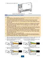
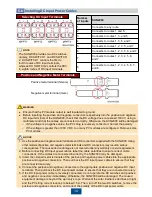
1. Connect the ground cable to the PE point
(on the chassis shell).
2. Connect the ground cable to the PV side
ground point.
Opening the Maintenance Compartment Door
5.4
Never open the host panel of the SUN2000.
Before opening the SUN2000 maintenance compartment door, turn off the downstream AC
output switch and the two bottom DC switches.
Reserved PE point
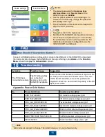
1. Remove the two security torx screws from the
maintenance compartment door using a security
torx wrench. (Set the two screws aside. Use the
idle ground screw on the chassis shell as the
standby screw, and the idle floating nut on the
chassis as the standby floating nut.)
2. Open the maintenance compartment
door and install the support bar.
WARNING
NOTE


