background image

9

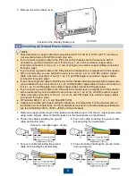
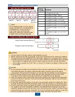
Ensure that the AC output power cable is connected securely. Otherwise, the SUN2000 may fail to 
operate or experience any fault that will cause the damage of the terminal block. For example, the 
SUN2000 may generate heat during operation due to unreliable connection.

2. Prepare OT terminals. 
3. Route the AC output power cable into the maintenance compartment.
4. Connect the AC output power cables and secure them using a socket wrench with an 

extension rod.

a. Three-core cable (excluding the 

ground cable and neutral wire)

c. Four-core cable (excluding the ground 

cable but including the neutral wire)

b. Four-core cable (including the ground 

cable but excluding the neutral wire)

d. Five-core cable (including the ground 

cable and neutral wire)

NOTICE

Summary of Contents for SUN2000-33KT-US

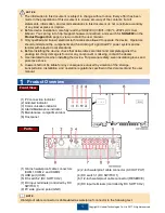
Page 1: ...HUAWEI TECHNOLOGIES CO LTD SUN2000 33KTL 36KTL 40KTL US Quick Guide Mounting Bracket Supplied with the SUN2000 Amphenol Helios H4 Issue 03 Part Number 31508086 Date 2017 11 06 ...

Page 2: ...he device check that deliverables are intact and complete against the packing list If any damage is found or any component is missing contact the dealer 5 Use insulated tools when installing the device For personal safety wear insulation gloves and protective shoes 6 Huawei shall not be liable for any consequence caused by violation of the storage transportation installation and operation regulati...

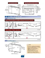
Page 3: ...000 on the mounting bracket connecting cables to the bottom of the SUN2000 and maintaining the SUN2000 in future it is recommended that the bottom clearance be between 600 mm 23 62 in and 730 mm 28 74 in Installation Angle 2 1 Wall mounted Installation and Normal Support mounted Installation Tilted Support mounted Installation NOTE ...

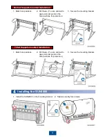
Page 4: ...ore installing the mounting bracket remove the security torx wrench from the mounting bracket and set it aside 3 Secure the mounting bracket Wall mounted Installation 1 Mark hole positions To prevent dust inhalation or contact with eyes wear safety goggles and an anti dust mask when drilling holes Wipe away any dust in or around the holes and measure the hole distance If the holes are inaccurately...

Page 5: ... holes You are advised to apply anti rust paint on the hole positions for protection 3 Secure the mounting bracket 1 Mark hole positions 2 Drill holes You are advised to apply anti rust paint on the hole positions for protection 4 4 Installing the SUN2000 1 Install the SUN2000 on the mounting bracket 2 Tighten security torx screws ...

Page 6: ...N m plastic or 6 25 N m metal Common Connection 1 Remove the locking cap and plug from the waterproof connector 2 Route the cable through the locking cap and then the waterproof connector 3 Install the cable 4 Tighten the locking cap 5 Check that the cables are connected correctly and securely Then seal the waterproof connectors and cable holes 6 Clear foreign matter from the maintenance compartme...

Page 7: ...ign matter from the maintenance compartment How to handle the bottom waterproof connectors depends on the connection method For details see Common Connection and Connection Through a Pipe Cables to the maintenance compartment interior are connected in the same way irrespective of which connection method is used The following uses common connection as an example Core wire Insulation layer Heat shri...

Page 8: ...earby ground point Connect the ground points of all SUN2000s in the same PV array to ensure equipotential connections to ground cables To enhance the corrosion resistance of the ground terminal apply silica gel or paint on it after connecting the ground cable 1 Connect the ground cable to the PE point on the chassis shell 2 Connect the ground cable to the PV side ground point Opening the Maintenan...

Page 9: ...L1 L2 L3 and N single core outdoor copper cables connected through a pipe If you connect a ground cable to the PE point in the maintenance compartment in the scenario with a neutral wire you are advised to use a five core L1 L2 L3 N and PE outdoor copper cable common connection or five L1 L2 L3 N and PE single core outdoor copper cables connected through a pipe OT terminal M8 L1 L2 L3 and N and M6...

Page 10: ...Prepare OT terminals 3 Route the AC output power cable into the maintenance compartment 4 Connect the AC output power cables and secure them using a socket wrench with an extension rod a Three core cable excluding the ground cable and neutral wire c Four core cable excluding the ground cable but including the neutral wire b Four core cable including the ground cable but excluding the neutral wire ...

Page 11: ...the positive and negative power cables into the appropriate positive and negative connectors Then pull back the DC input power cables to ensure that they are connected securely 4 Connect the positive and negative connectors to the appropriate positive and negative DC input terminals Then pull back the DC input power cables to ensure that they are connected securely 5 If the DC input power cable is...

Page 12: ... PLC CCO module to the AC power cable Installing the RS485 Communications Cable 5 8 1 When routing communications cables separate communications cables from power cables to prevent communication from being affected by signal interference 2 An RS485 cable can connect to either a terminal block or an RJ45 network port It is recommended that the RS485 cable connect to a terminal block Selecting a Com...

Page 13: ... signal 4 RS485B OUT RS485B RS485 differential signal 4 Install the terminal base on the terminal block and connect the shield layer to the ground point 5 Bind the communications cables When connecting the shielded cables choose whether to crimp the OT terminal based on site requirements RJ45 Network Port Connection You are advised to use a CAT 5E outdoor shielded network cable with an outer diame...

Page 14: ...and securely without open circuits or short circuits Yes No N A 4 AC output power cables are connected correctly and securely without open circuits or short circuits Yes No N A 5 DC input power cables are connected correctly and securely without open circuits or short circuits Yes No N A 6 The communications cables are connected correctly and securely Yes No N A 7 All pipes and the waterproof conn...

Page 15: ... input voltage of the corresponding MPPT circuit is higher than or equal to 200 V Off The SUN2000 disconnects from all PV strings or the DC input voltage of each MPPT circuit is less than 200 V Grid tied indicator Steady green The SUN2000 has connected to the power grid Off The SUN2000 does not connect to the power grid Communications indicator Blinking green on for 0 5s and then off for 0 5s The ...

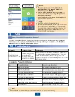
Page 16: ...supports only Bluetooth connection 3 Access the Huawei app store http appstore huawei com Google Play https play google com or App Store iOS search for SUN2000 and download the SUN2000 app software package 4 Connect a USB data cable or a Bluetooth module to the USB port of the SUN2000 to implement the communication between the SUN2000 and the app SUN2000 App 8 SUN2000 Bluetooth module Mobile phone...

Page 17: ...reen Symptom Possible Cause Suggestion The PV string is connected reversely The PV string cables are connected reversely during the SUN2000 installation Wait until the solar irradiance declines at night and the PV string current reduces to below 0 5 A Then turn off the two DC switches remove the positive and negative connectors and correct the polarity of the DC input power cable Appendix Power Gr...

Page 18: ...rier Huawei Technologies Co Ltd Huawei Industrial Base Bantian Longgang Shenzhen 518129 People s Republic of China www huawei com You can also log in to Huawei technical support website http support huawei com Google Play Huawei App Store Apple Store Support WeChat ...

Reviews: