


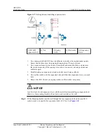
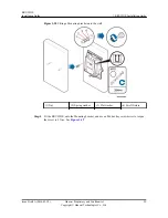


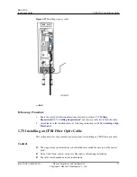


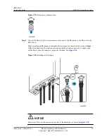


Figure 1-20
RRU3931E cable connections
(1) PGND cable
(2) CPRI fiber optic
cable
(3) Power cable
(4) RF Jumper
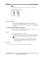
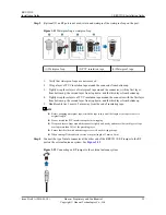
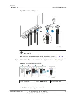
NOTE
When routing cables from a maintenance cavity, observe the following:
l
Route the power cable through the cable hole on the upper-layer rubber strip
l
Route the other cables (except power cables) through cable holes on the lower-layer rubber strip
preferentially
l
Route cables through cable holes on the same side of ports, and do not cross cables.
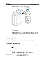
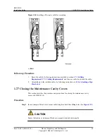
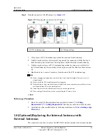
1.7.3 Opening the Maintenance Cavity Covers
This section describes the procedure and precautions for opening the maintenance cavity
covers of a RRU3931E.
Procedure
Step 1
Use an M6 hex key screwdriver to loosen the captive screw on both the maintenance cavity
covers. Open the maintenance cavity covers.
Figure 1-21
shows the maintenance cavity structure.
RRU3931E
Installation Guide
1 RRU3931E Installation Guide
Issue Draft A (2016-03-30)
Huawei Proprietary and Confidential
Copyright © Huawei Technologies Co., Ltd.
24


