Installation Manual – Antenna & Feeder System Installation
BTS3802C & RRU
Chapter 2
Installing RF Antenna & Feeder System
2-9
(1)
(2)
(3)
(4)
(5)
(6)
(7)
(8)
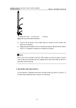
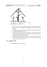
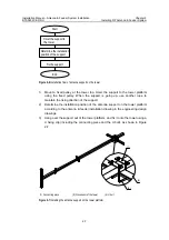
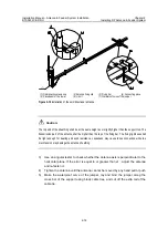
(1) Antenna lightning
rod
(2) Solder point
(3) Main supporting post 2
(4) Bolt M10×80
(5) Stiffener
(6) Main supporting post 1
(7) Mat of the support post
(8) Anchor of the stiffener
Figure 2-8
Structure of the antenna support on the roof
2.5.2 Installation Requirements
z
The connecting pieces for the stiffener shall be installed in the places in which
they do not impede adjustment of the antenna orientation and pitch angle.
z
The antenna support shall be perpendicular to the level plane.
z
For installation of the directional antenna on the roof, the antenna support shall
be equipped with a lightning rod and be connected with the lightning net of the
building.
z
For installation of the omnidirectional antenna on the roof, the antenna support
generally shall not be installed with a lightning rod. Instead, the lightning rod shall
be installed on a separate support.
z
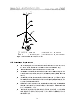
If a lightening rod is installed on the support also equipped with omnidirectional
antennas, it is required the antennas shall be hung over out of the support and
the distance shall be 1–1.5m.
z
The antenna support and all soldered parts shall be coated with the anti rusting
paint. All soldering joints shall be secure. There shall be no false soldering or
open solder point.

