background image

18

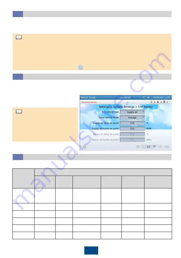
On the main screen, tap 

Settings 

>

System Settings 

>

T/H Sensor 

to change temperature and 

humidity control types or set points, and enable the humidity and temperature sensors for the 
corresponding aisles.. 

For initial power-on, the system enters the quick setting screen. Set the 

Language

Date format

Date

Time

Zone

Monitor mode

, and verifying the present voltage. For non-initial power-on, the 

LCD automatically enters the home screen.

To set 

T/H control type

Temp control 

mode

, cold aisle sensors 1, 2, and 3, 

and hot aisle sensors 1, 2, and 3, log in 
as the 

Admin

or 

Engineer

user. To set 

other parameters, log in as the 

Admin

Engineer

, or 

Operator

user.

NOTE

1. Users include 

Admin

Engineer

Operator

, and 

Guest

. The 

Admin

users have the highest 

permission, followed by the 

Engineer

Operator

, and 

Guest

users. The initial passwords for the 

Admin

Engineer

, and 

Operator

users are all 

000001

. The 

Guest 

user does not have a initial 

password. For system security purposes, change the preset password upon first login. 

2. After login to the system using a user name, the user right is valid when you touch the screen all 

the time. If you do not touch the screen, the user right is only valid for 3 minutes. To ensure 
security, manually log out by tapping        at the right corner of the home screen.

NOTE

Basic Settings

7.2

Temperature and Humidity Settings

7.3

(Optional) Operation Guide for Teamwork Connection

7.4

No.

Items

CAN 

networking

Teamwork 

address

Teamwork CAN 

resistor enable

Teamwork 

function

Total number 

of units

Number of 

running units

1

1

1

Yes

Enable

32

30 (2 standby 
smart cooling 
products)

2

1

2

No

Enable

N/A

N/A

3

1

3

No

Enable

N/A

N/A

……

……

……

……

……

……

……

31

1

31

No

Enable

N/A

N/A

32

1

32

Yes

Enable

N/A

N/A

Using thirty two smart cooling products in teamwork as an example: 

Summary of Contents for NetCol5000 C030H6B20 10020E1

Page 1: ...r bottom piping No Yes 168 2000 x 300 x 1000 30 Yes Top or bottom piping No Yes 172 2000 x 300 x 1100 30 Yes Top or bottom piping No Yes 174 2000 x 300 x 1200 NetCol5000 C030H7B20 10020E1 30 Yes Top or bottom piping Yes No 165 2000 x 300 x 1100 30 Yes Top or bottom piping Yes No 170 2000 x 300 x 1200 NetCol5000 C030H7A20 1E120E0 30 No Top or bottom piping No Yes 171 2000 x 300 x 1000 NetCol5000 C0...

Page 2: ...The picture uses NetCol5000 C030H6B2010020E1 as an example For the structure of other products refer to their respective structures 2 2 Material Preparations With the NetCol520 Without the NetCol520 ...

Page 3: ...nch made of EPDM or other material Auto drainpipe DN19 rubber hose or PPR pipe with BSPT 1 2 inch outer screw thread elbow Water inlet and outlet pipes Copper gate valve each for the main chilled water supply and return pipes above 2 0 MPa resistance Y shaped strainer above 2 0 MPa resistance 20 openings water pressure gauge gauge bend thermometer Recommended pipe when the NetCol520 is connected r...

Page 4: ...or equal to 58 mm this operation is not required 3 Install a shock absorbing bar 5 mm thick made of EPDM rubber at the bottom of the base 4 Control the soldering process to prevent an excessive error 5 L equals to the depth of the device 1 Read the user manual and instructions for product information before installation 2 The models described in this document are fully configured smart cooling pro...

Page 5: ...read adhesive to the first to third thread circles counting from the pipe outlet inward For external threads apply thread adhesive to the third to second last thread circles counting from the pipe outlet inward Based on the hardening property of yellow adhesive inject nitrogen and preserve the pressure only 8 hours after an adapter is connected 6 Install pagoda connectors Remove side panels Remove...

Page 6: ...is unavailable or not allowed transport the cabinet by manpower Six people are required Remove the side panel Four people carry the cabinet Force bearing area is shown in the figure The other two hold it to prevent tilting Then install the side panel No Name Inner Diameter 1 Ports for humidifier water inlet pipe 60 mm 2 Ports for signal cables 28 mm 3 Ports for the water pump and automatic condens...

Page 7: ...o the base and install conversion bracket and air baffle Obtain the screws for securing the equipment to the base from the fitting bag NOTE 3 Install the air baffle 2 Level the cabinet M10x25 4 PCS 30 N m Conversion bracket is no use when it is non anchored installation on an ESD floor NOTE ...

Page 8: ...3 Wrench an anchor bolt clockwise to elevate the cabinet or wrench an anchor bolt anticlockwise to lower it A cabinet leg can be adjusted within a range of 0 8 mm Combining Cabinets from Front and Rear Door 3 7 Optional Relocating the Baffle Plate 3 9 Optional Removing the Transport Fixing Metals 3 8 This step applies to the model with 1100 mm and 1200 mm depth and electric heater or water pump Pe...

Page 9: ...o be faulty as shown in the following figure 2 Use a 3 way valve to connect the main pipe 3 The main condensate pipe gradient should be 1 100 4 Keep at lest 25 mm away from pipe to pipe Install a pipe support every 2500 mm 5 Pipes are recommended to be wrapped with heat insulation foam Piping 4 1 Scenario Pipes Must Be Connected Optional Pipes to Be Connected Top drainage Water pump drainpipe Auto...

Page 10: ...served pipe and install DN19 rubber hose and the clamp required torque 4 N m Warp the thermal insulation foam 10 Connecting Auto drainpipe 4 3 Bottom water inlet scenario Top water inlet scenario Reserved pipe Rubber hose Thermal insulation foam ...

Page 11: ...d chloroprene adhesive 25 N m torque and PPR pipe or aluminum plastic pipe Connecting Water Pump Drainpipes 4 4 Bottom drainage scenario Top drainage scenario 11 PPR pipe or aluminum plastic pipe Thermal insulation foam Thermal insulation foam Water pump drainpipe Water pump drainpipe Thermal insulation foam ...

Page 12: ...valve is open 100 2 Open the main water inlet valve 3 Slowly open the exhaust valve to exhaust air accompanied by some chilled water from the exhaust hose 4 When air bubbles stop coming out of the hose opening turn the chilled water valve to the zero as air has been exhausted 5 Close the exhaust valve 12 Bottom Piping Connecting Water Inlet and Outlet Pipes 4 5 Leak Checking 4 6 Filling Water to E...

Page 13: ...corrugated pipes in the delivered accessories to separate strong current cables from weak current cables 2 Fasten power cable to the vertical pillar of rear door by cable ties every 150 mm to 200 mm 13 2 Electrical Ports of NetCol5000 C030H7 Teamwork networking port Remote shutdown cable port Humidity and Temperature T H Sensor port 1 Electrical Ports of NetCol5000 C030H6 Connecting Power Cables a...

Page 14: ...Top cabling Bottom cabling M6x16 1 PCS 3 N m M6x16 1 PCS 3 N m 14 ...

Page 15: ...ead screwdriver This step applies only to the NetCol5000 C030H7 The T H sensor must be 1 5 m above the floor It can be secured to the cabinet using cable ties or two M4 screws put through the holes in the sheet metal Then set the sensor address based on the sensor location For details see the following table Optional Setting the Power Switch 5 3 Connecting the T H Sensor 5 4 Optional Teamwork Netw...

Page 16: ...t is 3 seconds In the teamwork mode of cascading using an RS485 bus for monitoring it takes the host 3 seconds multiplied by N to collect data from N smart cooling products in the group For example the time needed for collecting data from four smart cooling products is 12 seconds If the host needs more time to collect data from all smart cooling products than what the host performance requires use...

Page 17: ...hat the pressure preservation and air tightness test for pipes have been completed Passed Failed 6 Check that the cabinet is grounded Passed Failed 7 Check that power cables and signal cables are correctly connected signal cables are protected in a corrugated pipe and bound securely and power cables are routed separately from signal cables Passed Failed 17 7 Powering On the System 1 Measure the in...

Page 18: ...perator and Guest users The initial passwords for the Admin Engineer and Operator users are all 000001 The Guest user does not have a initial password For system security purposes change the preset password upon first login 2 After login to the system using a user name the user right is valid when you touch the screen all the time If you do not touch the screen the user right is only valid for 3 m...

Page 19: ... in the network and remain it in No for other smart cooling products 4 Teamwork function Disable or enable the teamwork function If the teamwork function is disabled this device is operating according to its own control If the teamwork function is enabled this device works in harmony with others that in the same group 5 Total number of units Number of the precision smart cooling products in this g...

Page 20: ...e is free from leakage Set the valve of humidifier to 0 and press the drainage switch to OFF figure 5 9 Follow up Procedure 1 Install the cover on the main power wiring panel and secure the cover using M4 screws 2 Install the air filters 3 Close and lock the rear door 6 Set the opening of the chilled water valve to 100 The handle of the chilled water valve should be rotated to the maximum value 7 ...

Page 21: ...A high temperature alarm is generated for the inlet or outlet water or the communication with the inlet or outlet water temperature sensors has been interrupted Find the Cause 1 Locate the sensor at the same position on the upstream smart cooling product along the main pipe and check whether the temperature display is within a difference of 2º C compared with the sensor for which an alarm has been...

Page 22: ...ol5000 C030 In row Chilled Water Smart Cooling Product User Manual Simple Configuration Symptom The water level is under the low float bulb and the bulb moves properly The controller displays Full water or Drain abnormal Find the Cause After the float bulb is pressed down manually the alarm disappears in about 10 seconds which indicates that the float has become faulty Cause The float is faulty Tr...

Reviews: