


7
1
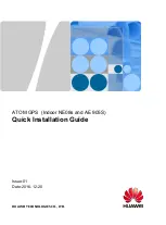
Assembling OT Terminals
Material: OT terminals (ring terminals) , heat-shrinkable tube and cable.
Strip a part of the jacket off the cable to expose the
conductor with a length of L1.
L1 = 23 mm to 25 mm
L1
Conductor
When stripping the jacket off the cable, do not
damage the metal conductor of the cable.
Press the end of the contact terminal on the
conductor by using the crimping tool.
Heat the heat-shrinkable tube by using a heat gun.
Lead the cable through the heat-shrinkable tube,
and then place the contact terminal on the
exposed conductor.
A: heat-shrinkable
B: OT terminals
•Close contact between the contact terminal and the end of
the jacket of the cable is required.
•When placing the contact terminal on the conductor
closely to the end of the jacket, ensure that the L2 part of
the conductor which sticks out of the contact terminal
cannot exceed 2 mm.
C: power cable
insulation layer
Heat gun
Do not overheat the heat shrink tube. Otherwise,
the insulation layer may be damaged.
CAUTION
CAUTION
CAUTION
Appendixes


