Step 4
Test the levels of the two test signals at the test point for upstream combined test signals.
Adjust the upstream attenuation tab to configure the upstream receive level to B.
----End
You can skip steps 3 and 4. Connect the CM to the RF OUT test point, enable the CM to go
online or lock the frequency in the upstream direction, and then adjust the upstream
attenuation bracket to enable the upstream Tx level of the CM to be A + 20.
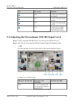
The following figure shows the location of the test points and attenuation brackets on a
combiner.
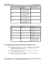
Bracket to Be Adjusted
Parameter to Be
Adjusted
Default value (dB)
ATT9
Level of upstream DOCSIS
signal of the RF OUT3.
0
ATT6
Level of upstream DOCSIS
signal of the RF OUT0.
0
ATT8
Level of upstream DOCSIS
signal of the RF OUT2.
0
ATT7
Level of upstream DOCSIS
signal of the RF OUT1.
0
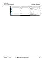
No.
Test point
Function
TP.5
Tests level of input signals
of TX0.
TP.6
Tests level of input signals
of TX1.
TP.10
Tests level of upstream
signals in RF OUT3.
MA5833-DD60
Hardware Commissioning Guide
5 Adjusting the Signal Level
Issue 01 (2018-12-26)
Copyright © Huawei Technologies Co., Ltd.
13

