4
Installing the CE6855 Switch
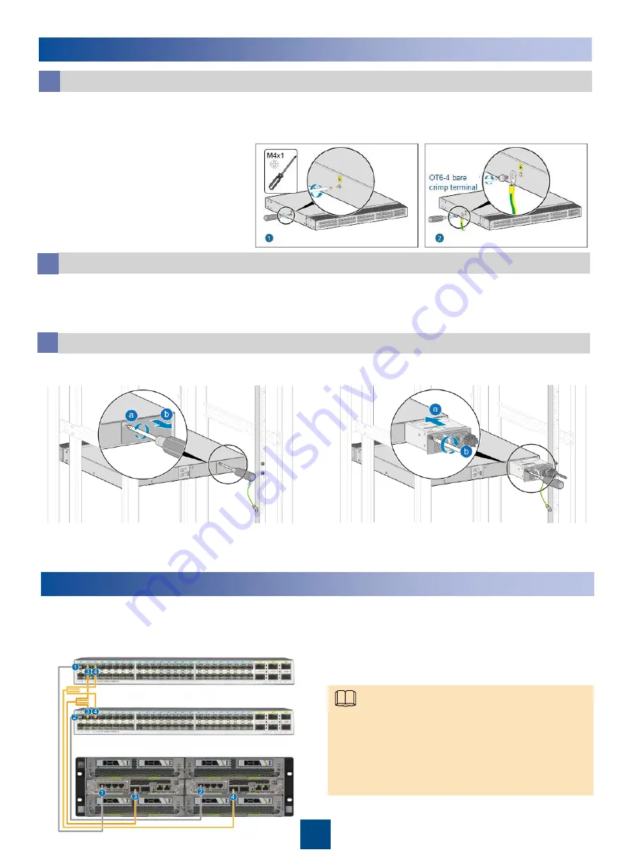
Install the PGND cable on the switch.
a
1. Use a Phillips screwdriver to
loosen the M4 screws on the
ground terminal of the switch.
2. Select a PGND cable near the
installation position.
3. Use the Phillips screwdriver to
secure one end of the OT6-4
bare crimp terminal of the PGND
cable to the ground terminal of
the switch.
b
b
1. Hold the switch with both hands and move it into the cabinet. Align the rear mounting ears
with the slide rails and slowly slide the switch along the slide rails.
2. Fasten the front mounting ears to the floating nuts with the Phillips screwdriver and M6 screws.
Install the power module and fan module.
c
Install the switch in the cabinet.
1. Remove the filler panel.
3. Install the fan module in the same way as installing the power module.
4. Connect the power cable to the power module.
Installing the Ethernet Cable
Connect one end of the Ethernet cable to the port (for connecting another NE) in the subrack
and the other end to another NE as required.
Optical fiber connections between the OSTA5.0 (3 U) subrack and the switch:
•
Cables 1 and 2: Used for connecting the LAN0 ports
on the two MSXA boards to the CE6855 and carrying
CGP O&M traffic.
•
Cables 3 and 4: Two of the 1-to-4 optical fibers. Used
for connecting the eFabric LAN0 ports on the two
MSXA boards to the CE6855 and carrying service
traffic and EPC O&M traffic.
2. Install the power module.
Note


