background image

DPU40D-N06A3, DBU20B-N12A3, and 
DBU50B-N12A1 Distributed Power System 
User Manual 

A Technical Specifications 


Issue 04 (2020-02-29) 

Copyright © Huawei Technologies Co., Ltd. 

60 


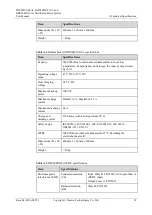
Item 

Specifications 

Harmonic current 

IEC 61000-3-2 

Voltage fluctuation 
and flicker 

IEC 61000-3-3 

Electromagnetic 
susceptibility 
(EMS) 

ESD 

IEC 61000-4-2 

Contact discharge: 6 kV; air discharge: 8 kV 

Electrical fast 
transient (EFT) 

IEC 61000-4-4 

AC power port: ±2 kV; DC power port: ±2 
kV; signal port: ±1 kV 

Radiated 
susceptibility (RS) 

IEC 61000-4-3 

80 MHz to 2.7 GHz: 10 V/m 

2.7 GHz to 6 GHz: 3 V/m 

Conducted 
susceptibility (CS) 

IEC 61000-4-6 

Power port: 10 V; signal port: 10 V 

Surge susceptibility 

IEC 61000-4-5 


AC power port: 6 kV in differential 
mode, 6 kV in common mode, 1.2/50µs 


DC power port: 2 kV in differential 
mode, 4 kV in common mode, 1.2/50µs 


Signal port: 0.5 kV in differential mode, 

2 kV in common mode, 1.2/50µs 

Voltage dip 

IEC 61000-4-11 


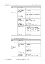
Table A-6


DBU20B-N12A3/DBU50B-N12A1 EMC specifications 

Item 

Specifications 

Electromagnetic 
interference (EMI) 

Conducted emission 
(CE) 

Class A, EN55032 

Radiated emission 
(RE) 

Class B, EN55032 

Electromagnetic 
susceptibility 
(EMS) 

ESD 

IEC 61000-4-2 

Power port: Contact discharge 8 kV, air 
discharge 15 kV 

Signal port: 2 kV 

Radiated 
susceptibility (RS) 

IEC 61000-4-3 

30 MHz to 2.7 GHz: 10 V/m 

Electrical fast 
transient (EFT) 

IEC 61000-4-4 

Power port ±2 kV, Signal port ±1 kV 

Summary of Contents for DBU20B-N12A3

Page 1: ...DPU40D N06A3 DBU20B N12A3 and DBU50B N12A1 Distributed Power System User Manual Issue 04 Date 2020 02 29 HUAWEI TECHNOLOGIES CO LTD ...

Page 2: ...tomer All or part of the products services and features described in this document may not be within the purchase scope or the usage scope Unless otherwise specified in the contract all statements information and recommendations in this document are provided AS IS without warranties guarantees or representations of any kind either express or implied The information in this document is subject to c...

Page 3: ...re defined as follows Symbol Description Indicates a hazard with a high level of risk which if not avoided will result in death or serious injury Indicates a hazard with a medium level of risk which if not avoided could result in death or serious injury Indicates a hazard with a low level of risk which if not avoided could result in minor or moderate injury Indicates a potentially hazardous situat...

Page 4: ...tween document issues are cumulative The latest document issue contains all the changes made in earlier issues Issue 04 2020 02 29 Modified 2 3 System Configuration Modified A Technical Specifications Issue 03 2019 11 28 Modified 1 Safety Precautions Modified A Technical Specifications Issue 02 2019 07 22 Update LIVE C APP content Issue 01 2019 06 30 This is the first official release ...

Page 5: ...verview 15 2 1 Introduction 15 2 2 Features 16 2 3 System Configuration 17 3 Components 19 3 1 PSU DPU40D N06A3 19 3 2 Lithium Battery DBU20B N12A3 DBU50B N12A1 23 4 Optional LIVE C APP 27 4 1 Installing the LIVE C APP 27 4 2 Logging In to the LIVE C APP 27 5 Maintenance 30 5 1 Preventive Maintenance 30 5 1 1 Exterior 30 5 1 2 Distributed Power Unit 31 5 1 3 Lithium Battery 31 5 1 4 Cable 32 5 2 R...

Page 6: ...ischarge Protection 37 5 2 17 Battery Cell N Fault 37 5 2 18 Discharge Overcurrent Protection 37 5 2 19 Charge Overcurrent Protection 38 5 2 20 Heater Fault 38 5 2 21 BMU Missing 38 5 3 Component Replacement 38 5 3 1 Replacing a Quick Connector PSU 39 5 3 2 Replacing a Quick Connector Lithium Battery 42 5 3 3 Replacing a PSU PSU Only 43 5 3 4 Replacing PSUs Interconnected PSUs 45 5 3 5 Replacing a...

Page 7: ...es or property damage are not covered under the warranty Follow local laws and regulations when installing operating or maintaining the equipment The safety instructions in this document are only supplements to local laws and regulations Huawei will not be liable for any consequences of the following circumstances Operation beyond the conditions specified in this document Installation or use in en...

Page 8: ...in the following figure Follow the specified procedures for installation operation and maintenance Ensure that bolts are tightened with a torque wrench and marked using red or blue color Installation personnel mark tightened bolts in blue Quality inspection personnel confirm if the bolts are tightened and then mark them in red The marks should cross the edges of the bolts as shown in the following...

Page 9: ... equipment area In the case of a fire immediately leave the building or the equipment area and turn on the fire alarm bell or make an emergency call Do not enter the building on fire in any case Do not stop using protective devices Pay attention to the warnings cautions and related precautionary measures in this document and on the equipment Promptly replace warning labels that have worn out Keep ...

Page 10: ...Indicates equipotential bonding This symbol is found with equipotential terminals inside equipment Indicates electrostatic discharge ESD This symbol is used in all electrostatic sensitive areas Before operating equipment in these areas wear ESD gloves or an ESD wrist strap Indicates that the equipment is safe to use at altitudes below 2000 m 6561 6 ft Indicates that the equipment is not safe to us...

Page 11: ...equipment Professionals personnel who are trained or experienced in equipment operations and are clear of the sources and degree of various potential hazards in equipment installation operation and maintenance Trained personnel personnel who are technically trained have required experience are aware of possible hazards on themselves in certain operations and are able to take protective measures to...

Page 12: ...re connecting the power supply ensure that cable connections are correct If the equipment has multiple inputs disconnect all the inputs before operating the equipment Cabling When routing cables ensure that a distance of at least 30 mm exists between the cables and heat generating components or areas This prevents damage to the insulation layer of the cables Do not route cables behind the air inta...

Page 13: ...that the cabinet is secured and will not tilt or fall down due to loss of balance which can cause personal injury or equipment damage Do not expose the equipment to flammable or explosive gas or smoke Do not perform any operation on the equipment in such environments Installation at Heights Working at heights refers to operations that are performed at least 2 meters above the ground Do not at heig...

Page 14: ...ghts Do not allow people to stay or pass under the area involving working at heights Inspect the scaffolding springboards and workbenches used for working at heights in advance to ensure that their structures are solid and not overloaded Dismantle the scaffolding from top down after finishing the job Do not dismantle the upper and lower layers at the same time When removing a part ensure that othe...

Page 15: ...ure that the pull ropes are secured and the ladder is held firm Before using a ladder check that it is intact and confirm its load bearing capacity Do not overload it Ensure that the wider end of the ladder is at the bottom or protective measures have been taken at the bottom to prevent the ladder from sliding Ensure that the ladder is securely positioned The recommended angle for a ladder against...

Page 16: ...t shift outside the legs of the ladder Drilling Holes When drilling holes into a wall or floor observe the following safety precautions Do not drill holes into the equipment Doing so may affect the electromagnetic shielding of the equipment and damage components or cables inside Metal shavings from drilling may short circuit boards inside the equipment Wear goggles and protective gloves when drill...

Page 17: ... sources transformers and heaters Excessive heat exposure may cause the batteries to explode Do not burn batteries Otherwise the batteries may explode To avoid leakage overheating fire or explosions do not disassemble alter or damage batteries for example insert sundries into batteries or immerse batteries in water or other liquids When replacing a battery use a battery of the same model or type I...

Page 18: ...cool environment with good ventilation which is away from high temperature and flammable materials and take precautions against fire Place and secure batteries horizontally Note the polarities when installing batteries Do not short circuit the positive and negative poles of the same battery or battery string Otherwise the battery may be short circuited When installing a battery string retain at le...

Page 19: ...handling a battery whose electrolyte leaks note that the leaking electrolyte may hurt human bodies If the electrolyte overflows follow the instructions of the battery manufacturer or neutralize the electrolyte by using sodium bicarbonate NaHCO3 or sodium carbonate Na2CO3 Lithium Battery The safety precautions for lithium batteries are similar to those for lead acid batteries except that you also n...

Page 20: ...A3 and DBU50B N12A1 Distributed Power System User Manual 1 Safety Precautions Issue 04 2020 02 29 Copyright Huawei Technologies Co Ltd 14 When maintenance is complete return the waste lithium battery to the maintenance office ...

Page 21: ...It is an indoor or outdoor wall mounted power solution that is highly efficient compact lightweight easy to install and does not require parameter configuration or maintenance The power system is designed for wireless base stations and supports online capacity expansion The DPU40D N06A3 converts AC or HVDC power into stable 48 V DC power The lithium battery supplies backup power to communications ...

Page 22: ...PSU integrates power rectification monitoring power distribution and surge protection The lithium battery integrates a battery management system BMS power distribution and surge protection Fan less design natural cooling Compact and lightweight Diverse installation scenarios Mounting on a pole wall channel steel or angle steel Side or flush mounting Flexible to combine Interconnected PSUs PSU plus...

Page 23: ...y online expansion to increase backup time Easy to maintain Remote monitoring 2 3 System Configuration Table 2 1 Typical system capacity specifications DPU40D N06A3 Number of Load Routes Number of PSUs PCS Number of Lithium Batteries PCS Power Backup Capacity Wh DBU20B Power Backup Capacity Wh DBU50B 3 1 0 0 0 6 2 0 0 0 3 1 1 960 2400 3 1 2 1920 4800 3 1 3 2880 7200 6 2 1 960 2400 6 2 2 1920 4800 ...

Page 24: ...es is 4180 W When three or more lithium batteries are configured the maximum output power of the lithium batteries is 2200 W x number of lithium batteries x 0 8 Lithium battery DBU50B N12A1 When one lithium battery is configured the maximum output power of the lithium battery is 3000 W When two lithium batteries are configured the maximum output power of the lithium batteries is 5700 W When three ...

Page 25: ... 19 3 Components 3 1 PSU DPU40D N06A3 Functions The PSU integrates power rectification distribution and monitoring It converts AC or HVDC power into stable 48 V DC power generates fault alarms and reports monitoring data to the upstream network management system NMS in real time The PSU supports communication with monitoring device through the MBUS ...

Page 26: ...on Indicator Color Status Description Running indicator Green Off The PSU has no power input no AC input and no battery input Steady on Start Self check Load instantaneous status during startup or upgrade Blinking at long intervals 0 5 Hz The PSU communicating with the host properly Blinking at short intervals 4 Hz The PSU is not communicating with the host properly Alarm indicator Red Off The PSU...

Page 27: ...ower input port 3 Load output port 1 4 Load output port 2 5 Load output port 3 6 Battery output port 7 COM_DIN port 8 COM_ALM port Power Ports Table 3 2 Power port description Port Fuse Specifications Function PWR 1 16 A quick connector excluding the fuse AC or DC input connects to the power supply LOAD1 LOAD2 LOAD3 3 40 A quick connector with replaceable fuses DC output connect to loads BAT 1 40 ...

Page 28: ...5200 bit s auto negotiation YDN protocol or master slave protocol ModBUS protocol Communicates with upstream monitoring equipment CAN2 0 Communicates with a cascaded PSU Figure 3 3 COM_DIN port pins Table 3 4 COM_DIN port pin definitions Pin Signal Name Description 1 7 NC NC 8 CANH CAN data transmission and reception H 9 CANL CAN data transmission and reception L Figure 3 4 COM_ALM port pins Table...

Page 29: ... data over RS485 negative 9 RS485_RX Northbound receives data over RS485 positive 10 RS485_RX Northbound receives data over RS485 negative 11 ALM4 A PSU or a lithium battery generates a recoverable alarm 12 ALM4 13 Reserved Reserved 14 CANH CAN data transmission and reception H 15 CANL CAN data transmission and reception L 3 2 Lithium Battery DBU20B N12A3 DBU50B N12A1 Functions The lithium battery...

Page 30: ...p self check loading activation board power on when no software is loaded Blinking slowly 0 5 Hz The lithium battery is communicating properly with monitoring equipment Blinking fast 4 Hz The lithium battery fails to communicate with monitoring equipment Alarm indicator Red Off The lithium battery is proper Steady on Board Hardware Fault Heater Fault Battery Cell N Fault Address Conflict Blinking ...

Page 31: ...COM_IN OUT port 3 Battery output port 1 4 Battery output port 2 Power Ports Table 3 7 Power port description Port Fuse Specifications Function BAT1 BAT2 2 80A quick connector excluding the fuse Battery output port Communications Ports Table 3 8 Communications port description Communications Port Communications Protocol Function COM_IN COM_OUT CAN2 0 Communicates with a PSU or with a cascaded lithi...

Page 32: ...ssue 04 2020 02 29 Copyright Huawei Technologies Co Ltd 26 Figure 3 7 COM_IN COM_OUT port pins Table 3 9 COM_IN OUT port pin definitions Pin Signal Description 1 2 NC NC 3 CAN_H CAN data transmission and reception H 4 6 NC NC 7 CAN_L CAN data transmission and reception L 8 GND Protective ground ...

Page 33: ... function and the connection mode is Bluetooth connection or WiFi connection Procedure Step 1 Obtain the latest LIVE C APP installation package from Huawei technical support Step 2 Install the LIVE C APP on the mobile phone Figure 4 1 LIVE C APP icon End 4 2 Logging In to the LIVE C APP Prerequisites You have obtained the LIVE C APP user name and password The mobile phone should be within 10 m awa...

Page 34: ...the login screen Figure 4 2 Login Screen Step 3 Tap Bluetooth connection in the login screen of the APP to search and connect for power equipment with Bluetooth nearby The power equipment SN and Bluetooth name have the same last six digits Step 4 Enter the user name and password initial user name liveapp initial password Changeme_123 After the first login change the password in time to ensure acco...

Page 35: ...50B N12A1 Distributed Power System User Manual 4 Optional LIVE C APP Issue 04 2020 02 29 Copyright Huawei Technologies Co Ltd 29 Step 5 Tap Login to access Main Function Menu and view the operating parameters of the power equipment End ...

Page 36: ... Exterior Table 5 1 Device exterior maintenance No Item Possible Fault Cause Suggestion 1 Check whether the device coating flakes off or is scratched Scratches occur during movement or the cabinet is manually damaged Repaint and repair the exterior 2 Check whether rust or corrosion exists Scratches occur during movement or the cabinet is manually damaged Repaint and repair the exterior 3 Check whe...

Page 37: ...atus normal off Steady on Rectifier Fault Monitoring Address Conflict Monitoring Unit Fault Blinking at short intervals 0 5 Hz Rectifier Protection Power off Communication Failure Rectifier Power Failure Parallel Fail AC Overvoltage or Undervoltage 1 If multiple PSUs are connected in parallel check that the communications and power cables are properly connected between them 2 Replace the PSU 5 1 3...

Page 38: ...tection Overtemperatur e protection Low Temperature Protection Abnormal shutdown Charge Overcurrent Protection Discharge Overcurrent Protection Handle the alarm based on the alarm type 5 1 4 Cable Table 5 4 Cable maintenance No Item Possible Fault Cause Suggestion 1 Check whether signal cables and power cables are separately bound Cables are not properly installed Install cables properly and bind ...

Page 39: ...the blinking frequency of the indicator If the indicator blinks at 4 Hz replace the module If the indicator blinks at 0 5 Hz rectify the fault onsite This method applies to scenarios with the NMS 5 2 1 AC Power Failure Possible Causes The mains power fails The AC input circuit breaker is OFF The AC input power cable is loose Solution 1 Measure the AC input voltage If the voltage is abnormal rectif...

Page 40: ...t Solution 1 Check whether the indicator on the rectifier is red If so replace the rectifier 2 Check whether the DC overvoltage alarm threshold is correctly set If not adjust it based on site requirements 5 2 5 DC Undervoltage Possible Causes The battery voltage is below the DC undervoltage alarm threshold The DC undervoltage alarm threshold is incorrectly set The DC output is short circuited Solu...

Page 41: ...ces external overvoltage Solution 1 Check whether the parallel power cable between rectifiers is loose If so secure the cable 2 Check whether the system output voltage is excessively high If so disconnect the parallel cable check the output voltage of each rectifier locate the rectifier with abnormally high output voltage and replace it 5 2 9 Rectifier Power Failure Possible Causes The upstream in...

Page 42: ... the cable 5 2 12 Board Hardware Fault Possible Cause The battery control board is faulty Solution Replace the faulty module 5 2 13 Low Temperature Protection Possible Causes The battery has discharged for a long period in a low temperature environment The battery is powered on for the first time and the temperature does not rise to above 0 C The battery heater is faulty Solution Check whether the...

Page 43: ... equalized and float charge voltages are correctly set see the appendix Technical Specifications If not adjust the settings based on site requirements 2 Check whether the PSU output voltage is excessively high If it is higher than the configured equalized or float charge voltage and cannot be adjusted replace the PSU 5 2 16 Overdischarge Protection Possible Cause The battery capacity is low due to...

Page 44: ...he load of the power system 2 Check whether the load is short circuited If so rectify the fault 5 2 19 Charge Overcurrent Protection Possible Cause Internal hardware is faulty Solution Replace the faulty module 5 2 20 Heater Fault Possible Cause The heater is faulty Solution Replace the faulty module 5 2 21 BMU Missing Possible Causes The battery communications cable is loose The battery power cab...

Page 45: ...tch off the upstream input circuit breaker After replacing a module use the quick connectors on the new module to prepare cables For details see 5 3 1 Replacing a Quick Connector PSU and 5 3 2 Replacing a Quick Connector Lithium Battery The PSU and lithium battery can be mounted on a small or large pole wall channel steel or angle steel The following figure shows the mounting kits Figure 5 1 Mount...

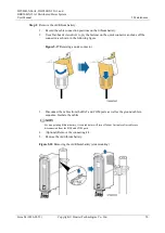
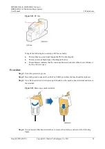
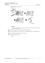
Page 46: ...move the cable Figure 5 2 Removing the old quick connector 6 mm2 core diameter Figure 5 3 Removing the old quick connector 6 mm2 core diameter Step 4 Install the new quick connector 1 Remove the quick connector from the new PSU and assemble the cable with the connector 2 Install the assembled quick connector at the corresponding port of the new PSU based on the cable connection position you have r...

Page 47: ... diameter 1 Scale line Figure 5 5 Assembling the new quick connector 6mm2 core diameter 1 Scale line 2 Bare crimp terminal 3 Crimping tool 4 Heat shrink tubing Step 5 Use waterproof tape to seal the cable connector Step 6 Switch on the upstream input circuit breaker for the PSU Step 7 Take off the protective gloves End Follow up Procedure Pack the faulty component and return it to the local Huawei...

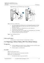
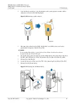
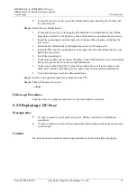
Page 48: ... Switch off the upstream input circuit breaker for the lithium battery Step 3 Remove the old quick connector 1 Record the cable connection position on the old lithium battery 2 Remove the quick connector from the old lithium battery and remove the cable Figure 5 6 Removing the old quick connector Step 4 Install the new quick connector 1 Remove the quick connector from the new lithium battery and a...

Page 49: ...e faulty component and return it to the local Huawei warehouse 5 3 3 Replacing a PSU PSU Only Prerequisites You have obtained a pair of protective gloves an inner hex torque screwdriver a flat head screwdriver a Phillips screwdriver and waterproof tape You have prepared a new PSU Procedure Step 1 Put on the protective gloves Step 2 Switch off the upstream input circuit breaker for the PSU Step 3 R...

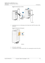
Page 50: ...in sequence Insulate the cables 4 Remove the old PSU Figure 5 9 Removing the old PSU flush mounting 5 Loosen the four screws on the hanging kit on the right side or rear of the PSU and take off the hanging kit Step 4 Install the new PSU 1 Secure the hanging kit to the right side or rear of the new PSU and tighten the four screws 2 Install the new PSU 3 Connect the ground cable as well as the cable...

Page 51: ... obtained a pair of protective gloves an inner hex torque screwdriver a flat head screwdriver a Phillips screwdriver and waterproof tape You have prepared new PSUs Procedure Step 1 Put on the protective gloves Step 2 Switch off the upstream input circuit breaker for the PSUs Step 3 Remove the old PSUs 1 Record the cable connection positions on the PSUs 2 Use a flat head screwdriver to pry the fast...

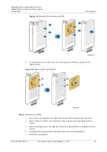
Page 52: ...t Huawei Technologies Co Ltd 46 Figure 5 11 Removing the old PSUs 5 Loosen the four screws on the hanging kit on the right side of the PSUs and take off the hanging kit Figure 5 12 Removing the hanging kit 6 Remove the connecting kit 7 Loosen the four screws that secure the PSUs to the connecting kit and take off the PSUs ...

Page 53: ...e off the connecting kit Figure 5 14 Removing the connecting kit Step 4 Install the new PSUs 1 Secure the connecting kit to the right side of a new PSU and tighten the four screws 2 Secure another new PSU to the right side of the connecting kit and tighten the four screws 3 Secure the hanging kit to the right side of the interconnected PSUs and tighten the four screws 4 Install the interconnected ...

Page 54: ...Pack the removed component and return it to the local Huawei warehouse 5 3 5 Replacing a PSU PSU Plus Lithium Battery Prerequisites You have obtained a pair of protective gloves an inner hex torque screwdriver a flat head screwdriver a Phillips screwdriver and waterproof tape You have prepared a new PSU Procedure Step 1 Put on the protective gloves Step 2 Switch off the upstream input circuit brea...

Page 55: ...hten the four screws 2 Install the connecting kit 3 Connect the ground cable as well as the cables to the COM BAT LOAD and PWR ports in sequence based on the recorded information 4 Use waterproof tape to seal the cable connections Step 5 Switch on the upstream input circuit breaker for the PSU Step 6 Take off the protective gloves End Follow up Procedure Pack the removed component and return it to...

Page 56: ...ner on the quick connector and take off the connector as shown in the following figure Figure 5 17 Removing a quick connector 3 Disconnect the cables from the BAT and COM ports as well as the ground cable in sequence Insulate the cables For an operating lithium battery its run indicator will turn off about 3 minutes after cables are disconnected from the BAT and COM ports 4 Optional Remove the con...

Page 57: ... the ground cable as well as the cables to the COM and BAT ports on the lithium battery in sequence based on the recorded information 5 Use waterproof tape to seal the cable connections Step 4 Take off the protective gloves End Follow up Procedure Pack the removed component and return it to the local Huawei warehouse 5 3 7 Replacing a Lithium Battery PSU Plus Lithium Battery Prerequisites You have...

Page 58: ...d COM ports as well as the ground cable in sequence Insulate the cables For an operating lithium battery its run indicator will turn off about 3 minutes after cables are disconnected from the BAT and COM ports 4 Record the cable connection positions on the lithium battery Disconnect the cables from the BAT and COM ports as well as the ground cable in sequence Insulate the cables 5 Remove the conne...

Page 59: ...attery and tighten the four screws 5 Install the connecting kit 6 Connect the ground cable as well as the cables to the COM and BAT ports on the lithium battery in sequence based on the recorded information 7 Connect the cables to the PSU Connect the ground cable as well as the cables to the COM BAT LOAD and PWR ports in sequence based on the recorded information 8 Use waterproof tape to seal the ...

Page 60: ...of burning on the fuse The multimeter indicates that the resistance between both ends of the fuse is infinite or the fuse circuit is open Procedure Step 1 Put on the protective gloves Step 2 Record the quick connector for a BAT or LOAD port where the fuse should be replaced Step 3 Use a flat head screwdriver to prize up the buckle on the quick connect terminal and remove the terminal Figure 5 23 R...

Page 61: ...s shown in the preceding figure when the flat head screwdriver is turned to Open the flat head bolt ejects Then remove the fuse Step 5 Install the new fuse in a reverse order of the removal procedure Step 6 Connect the quick connector to the BAT or LOAD port based on the recorded information Step 7 Use waterproof tape to seal the cable connections Step 8 Take off the protective gloves End ...

Page 62: ... DBU50B N12A1 60 m to 4000 m When the altitude ranges from 2000 m to 4000 m high temperature derating applies and the operating temperature decreases by 1 C for each additional 200 m Class C environments refer to sea environments or outdoor land environments with simple shielding measures near pollution sources If a site is near a pollution source it is at most 3 7 km away from salt water such as ...

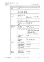
Page 63: ...c distortion THD 5 100 load HVDC input Input voltage 90 400 V DC DC output Output voltage range 42 V DC to 58 V DC Default output voltage With DBU20B N12A1 DBU20B N12A2 or without lithium batteries 54 5 V DC With DBU20B N12A3 DBU25 N12A1 DBU40B N12A2 or DBU50B N12A1 57 V DC Regulated voltage precision 0 6 Ripple and noise 200 mVp p Current sharing imbalance 5 20 100 load AC input protection AC inp...

Page 64: ... IP65 Safety design IEC62368 1 IEC EN 60950 22 IEC60950 1 GB4943 2011 YD T 1436 2014 MTBF 500 000 hours Ambient temperature 25 C Table A 3 Lithium battery DBU20B N12A3 specifications Item Specifications Capacity 960 Wh Due to external environmental factors such as temperature transportation and storage the capacity may deviate by 5 Operating voltage range 47 V DC to 57 V DC Float charging voltage ...

Page 65: ...ange 47 V DC to 57 V DC Float charging voltage 54 5 V DC Maximum backup power 3000 W Maximum charge current Default 10 A Maximum 25 A Maximum discharge current 64 A Charge and discharge cycles 1200 times ambient temperature 25 C Safety design IEC60950 1 IEC62368 1 IEC EN 60950 22 IEC 62619 GB4943 2011 UN38 3 MTBF 500 000 hours Ambient temperature 25 Excluding the electrochemical cell Dimensions H ...

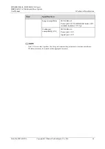
Page 66: ... CS IEC 61000 4 6 Power port 10 V signal port 10 V Surge susceptibility IEC 61000 4 5 AC power port 6 kV in differential mode 6 kV in common mode 1 2 50µ s DC power port 2 kV in differential mode 4 kV in common mode 1 2 50µ s Signal port 0 5 kV in differential mode 2 kV in common mode 1 2 50µ s Voltage dip IEC 61000 4 11 Table A 6 DBU20B N12A3 DBU50B N12A1 EMC specifications Item Specifications El...

Page 67: ...td 61 Item Specifications Surge susceptibility IEC 61000 4 5 Power port 2 kV in differential mode 4 kV in common mode 1 2 50 µ s Conducted susceptibility CS IEC 61000 4 6 Power port 10 V Signal port 10 V Note 1 This is a class A product In a living environment this product may cause radio interference Therefore users may be required to take appropriate measures ...

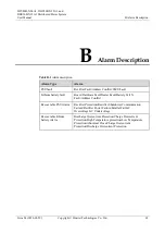
Page 68: ...t Lithium battery fault Board Hardware Fault Heater Fault Battery Cell N Fault Address Conflict Recoverable PSU Alarm Rectifier Protection Rectifier Shutdown Communication Failure Rectifier Power Failure Parallel Fail AC Overvoltage AC Undervoltage Recoverable lithium battery Alarm Discharge Overcurrent Protection Charge Overcurrent Protection High Temperature protection Low Temperature Protection...

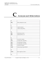
Page 69: ...breviations B BMS battery management system C CE conducted emission CS conducted susceptibility D DPU distributed power unit DBU distributed battery unit E EFT electrical fast transient EMC electromagnetic compatibility EMI electromagnetic interference EMS electromagnetic susceptibility ESD electrostatic discharge ESMU energy storage management unit H HVDC high voltage direct current M ...

Page 70: ...and DBU50B N12A1 Distributed Power System User Manual C Acronyms and Abbreviations Issue 04 2020 02 29 Copyright Huawei Technologies Co Ltd 64 MTBF mean time between failures P PSU power supply unit R RS radiated susceptibility ...

Reviews: