LP-743 Rev. 000 Rel. 000 Date 8.25.20
7
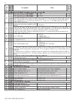
Table 3 - Critical cascade parameters to be configured at each Follower boiler. See E. Complete Cascade Technical Menu Parameters for a complete
list of parameters.
Parameter
Description
Value
Default Setting
34.10.3
Emergency Setpoint
68-179°F
113°F
Sets Follower boiler operating temperature when communication with Master is lost. Can also be adjusted via the CH +/- buttons of
the respective boiler, while operating in Emergency mode.
Part 3 - Cascade Wiring
WARNING
!
ELECTRICAL SHOCK HAZARD – To ensure safety, turn off electrical
power supply at service entrance panel before making any electrical
connections to avoid possible electric shock hazard. Failure to do so
could result in property damage, serious personal injury, or death.
Jumping out control circuits or components WILL VOID product
warranty and can result in property damage, personal injury, or
death.
Install wiring and electrically ground boiler in accordance with
the installation manual, the authority having jurisdiction or, in
the absence of such an authority, follow the National Electrical
Code, NFPA 70, and/or CSA C22.1 Electrical Code-Part 1 in Canada.
Failure to follow all applicable local, state, and national regulations,
mandates, and building supply codes for guidelines to install the
electrical power supply could result in property damage, serious
personal injury, or death.
It is of extreme importance that this unit be properly grounded. It
is very important that the building system ground is inspected by
a qualified electrician prior to making this connection. Electrical
power must only be turned on when the boiler is completely filled
with cold water. Failure to follow these instructions could result in
component or product failure, serious injury, or death.
CAUTION
!
Label all wires prior to disconnecting when servicing the boiler.
Wiring errors can cause improper and dangerous operation.
Failure to follow these instructions may result in property damage
or personal injury.
1. Connecting Power (120V) for DHW and CH Circulators
NOTE:
The CH and downstream IWH circulators MUST BE CONNECTED
to the Master Boiler to ensure proper operation.
To connect power for the CH and DHW external pump at the boiler
junction box:
1. Shut off the power supply at the boiler and at the circuit breaker.
2. Shut off the gas at the manual shutoff.
3. Remove the boiler front cover.
4. Disconnect the three clips and open the junction box
5. Insert the circulator power cable through the hole in the side
panel; use an appropriate strain relief/conduit hub to secure the
cable to the side panel.
6. Connect the cable on the connector CN5 (CH pump) and CN4
(DHW pump). See Electrical Wiring Diagram, Figure 3.
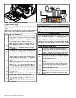
Figure 4 - 120V Connections for DHW and CH Circulators
2. Low Voltage Wiring Connections
To access the low voltage wiring connections:
1. Shut off the power supply at the boiler and at the circuit breaker.
2. Shut off the gas at the manual shutoff.
3. Remove the boiler front cover.
4. Remove the screw securing the control panel to the cross-member
(not applicable for ELU-85WBN, 120WBN, 120WCN, and 150WCN
models.
5. Push in the tabs and pull the control panel housing forward.
6. Disconnect the two clips. See Figure 4.
FUSE 5AT
POWER-IN
CN1
CN6
5
N
C
4
N
C
DHW
PUMP
CH
PUMP
FUSE
5
AT
N
N
DHW PUMP
L
N
CH PUMP
DHW PUMP
L
CH PUMP
L
NOTE:
Some newer thermostat models may draw too much
power from the boiler and will require an additional power supply
to operate properly. Review the instructions provided with the
thermostat to determine if an additional power supply is needed.
Failure to do so could result in improper boiler and/or thermostat
operation.
CAUTION
DO NOT CONNECT 120V TO ANY CONTROL WIRING CONNECTION!
DOING SO WILL RESULT IN IMPROPER OPERATION AND POSSIBLE
DAMAGE TO THE BOILER. SUCH DAMAGES ARE NOT COVERED BY
PRODUCT WARRANTY!
NOTE:
Figures 1 and 2 are provided as further references for wiring
cascade systems.
7. Verify that the new cable is correctly positioned inside the
control panel.
8. Reconnect the cover of the junction box.
9. Reinstall the boiler front cover
10. Restore gas to the boiler.
11. Restore power to the boiler.
Figure 5 - Releasing the Two Clips
7. Open the control panel cover to have access to the main PCB.
See Figure 5.


