


LP-743 Rev. 000 Rel. 000 Date 8.25.20
5
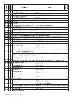
Part 2 - Cascade Control Set-Up
When setting up a cascade system, one boiler must be configured as a Master and the other boilers must be configured as Followers.
Establishing Boilers as Master and Followers:
NOTE:
Disconnect the WiFi PCB on each Follower boiler prior to setting up the cascade system. Only the Master boiler should be connected
to WiFi.
NOTE:
Start with all boilers powered OFF and with no wires connected to each boiler’s BUS connection.
1. Disconnect WiFi PCBs
- Permanently disconnect the WiFi PCB on each Follower boiler. Only the Master boiler can be connected to
WiFi.
2. Establish the Cascade Master
- Connect power to the boiler chosen as the Master. Enter the Technical Menu and set parameter 0.4.6
= b-MAS. Connect the System Sensor at “SYS” of the Master boiler with the SYS connector. See Part 3 - Cascade Wiring. The System
Sensor and SYS connector are included in this kit.
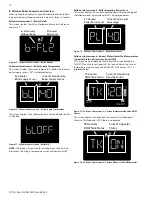
3. Establish Followers
- Connect power to the boiler chosen as Follower #1. Enter Technical Menu and set parameter 0.4.6 = b-FL1.
Repeat for remaining Follower boilers, taking care to set a unique value for each Follower, e.g. “b-FL2” through b-FL7”.
NOTE:
Each Follower must have a unique address. Giving boilers the same address will result in a Configuration Conflict (CONFL) error
code.
4. Establish Communication
- DISCONNECT POWER TO ALL BOILERS. Daisy-chain (connect in parallel) the BUS terminal of all boilers
with the BUS connectors included in this kit. Take care to maintain the correct polarity of “B” and “T” terminals. Connect power to all
boilers.
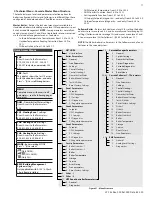
Program the Cascade System (Master Boiler):
The following parameters must be configured at the boiler configured as the Master (0.4.6 = b-MAS).
NOTE:
Set parameter 0.4.6 prior to adjusting other settings using the Establishing Boilers as Master and Followers procedure. Menu level 25
is not accessible unless 0.4.6 is set to b-MAS.
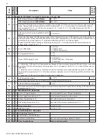
Parameter
Description
Value
Default Setting
0.4.6
Cascade Boiler Address (Master boiler must be set to b-MAS)
UNDEF = undefined, b-SIN = single boiler,
b-MAS = master boiler,
b-FL1 = Follower #1 boiler, b-FL2 = Follower #2,
b-FL3 = Follower #3, b-FL4 = Follower #4,
b-FL5 = Follower #5, b-FL6 = Follower #6,
b-FL7 = Follower #7
b--SIN
2.0.1
DHW Preheating
0 = Disabled, 1 = Enabled
1
Enables / disables DHW Comfort Function on WCN models (not applicable to WBN models) - see par. 25.2.1.
NOTE:
When connected
to a cascade system, DHW COMFORT Function is automatically turned on.
2.2.8
Combi Version -
WCN
Models
- DO NOT MODIFY
0 = Combi
0
Boiler Version -
WBN Models
Type of DHW control for Upstream IWH
1 = Storage with Tank Sensor
2 = Storage with Aquastat
2
Applicable when an Upstream IWH is connected directly to the Master boiler. Not applicable for WCN models.
NOTE: An Upstream IWH cannot be connected to a Master boiler when there is a Downstream / System IWH, i.e. when 25.2.2 = 1 or
2.
2.10.3
Emergency Setpoint
68-179°F
113°F
Sets Master boiler operating temperature when there is a malfunction of the BUS circuit. Can also be adjusted via the CH +/- but-
tons of the respective boiler, while operating in Emergency mode.
4.2.0
Temperature Range of CH System (Zone 1 – TT1)
0 = Low Temp (68-122°F)
1 = High Temp (86-179°F)
1
Establishes range of parameters 4.2.5 and 4.2.6. Refer to parameter 5.2.0 and 6.2.0 for CH Zone 2 and 3.
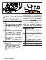
Figure 3 - Disconnect the WiFi PCB on each Follower Boiler
CN18
1
1
CN1
FUSE 5A
CN5
1
CN24
CN4
1
CN8
CN10
1
CN6
1
CN
3
CN
2
CN7
CN9
CN23
1
CN2
0
1
CN1
2
1
CN1
9
1
1
CN2
6
CN2
2
CN
16
BUS
T B
5V IN
OD TNK
SYS TT1
TT2
120V
120V 120V
120V
120V 120V
N
G
L
120 V
AC
GATEWAY WIFI
Rd
Wh
Bl
Bl
Rd
Rd
Br
Br
Bl
Gry
Bl
Bk
Bk
Bk
Rd
Rd
Wh
Br
Br
Br
Bk
Bk
Br
Wh
Water
pressure
switch
D.H.W.
temperature
sensor
D.H.W.
Flow
sensor
Flue temp.
probe
Return temp.
probe
Outlet
temp. probe
Gr
Wh
Bk
Br
Disconnect here on
every Follower boiler