LP-743 Rev. 000 Rel. 000 Date 8.25.20
8
3. Wiring a Cascade System
NOTE:
Disconnect the WiFi PCB on each Follower boiler prior to setting
up the cascade system. Only the Master boiler should be connected
to WiFi.
NOTE:
Use the Establishing Boilers as Masters and Followers procedure,
outlined in Part 2, when connecting boilers together on the BUS.
Failure to follow these instructions will result in improper system
operation, wasted time, money, and possible property damage
and personal injury. Such damages ARE NOT covered by product
warranty.
CN1
Cascade
Connection
Outdoor
Sensor
Tank temp.
probe
System
Sensor
Room Thermostat
1
2
3
4
5
6
7
BUS
T B
5V IN
OD TNK
SYS TT1
TT2
120V
120V 120V
120V
120V 120V
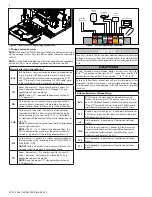
Figure 7 - Low Voltage Wiring Connections
Ensure cascade wiring between boilers always runs from the
BUS “T” connection to the next BUS “T” connection, and BUS “B”
connection to the next BUS “B” connection. “T” to “T”; “B” to “B”.
NOTICE
Take care to route the BUS communication cables and other low
voltage wiring away from line voltage cables to avoid electrical
interference which can cause operation issues or damage the main
PCB.
Master Boiler Low Voltage Wiring
BUS
BUS Network - Communication between cascaded boilers
(up to 8) and/or HTP Room Sensors (up to 3) and/or one
HTP Multifunctional Kit. Maintain correct polarity of “B”
and “T” terminals. Use a minimum of 20 AWG cable, prefe-
rably twisted pair, up to a maximum of 164 feet.
TT2
Room Thermostat 2 - Dry contact input for System CH
Zone 2 demands. Parameters 5.1.0 through 5.7.5 are
applicable to Zone 2 demands.
NOTE:
Zone 1 (TT1) demands take priority over Zone 2
(TT2) demands.
OD
Outdoor Sensor - Connect to factory provided outdoor
sensor to allow Automatic CH Temperature Control (or
connect Master boiler to WiFi and use Internet Weather).
TNK
Tank Sensor or Aquastat - Connect to a tank sensor or
Aquastat installed in a Downstream IWH heated by the
entire cascade system and set via 25.2.2. Or, installed in
an Upstream IWH connected to the Master boiler and set
via 2.2.8.
NOTE:
The Master boiler cannot heat both a Downstream
and an Upstream IWH.
NOTE:
If 25.2.2 = 1 or 2, the Master boiler considers the
IWH to be Downstream and uses the entire cascade to
service it - regardless of the setting of parameter 2.2.8.
SYS
System Sensor – Connect to a system sensor installed on
the supply line of the secondary loop – DO NOT INSTALL
IN PRIMARY LOOP.
NOTICE:
Failure to install a system sensor will cause the
cascade system to operate in Emergency Mode.
TT1
Room Thermostat 1 – Dry contact input for System CH
Zone 1 demands. Parameters 4.1.0 through 4.7.5 are
applicable to Zone 1 demands.
NOTE:
Zone 1 demands (TT1) take priority over Zone 2
(TT2) demands.
Follower Boiler Low Voltage Wiring
BUS
BUS Network - Communication between cascaded
boilers (up to 8) and/or HTP Room Sensors (up to 3) or
one HTP Multifunctional Kit. Maintain correct polarity of
“B” and “T” terminals. Use a minimum of 20 AWG cable,
preferably twisted pair, up to a maximum of 164 feet.
TT2
Auxiliary Limit Switch Input – Input does not function as
a CH Zone 2 input, but functions as a limit switch input
with parameter 34-40.2.3 = 0.
OD
Not Applicable - Input does not function on Follower
boilers.
TNK
Tank Sensor or Aquastat - Connect to a tank sensor or
Aquastat installed in an Upstream IWH connected to
the respective Follower boiler. Set to Tank Sensor or
Aquastat via parameter 34-40.2.8.
SYS
Not Applicable - Input does not function on Follower
boilers.
TT1
Not Applicable - Input does not function on Follower
boilers.
Figure 6 - Access to Low Voltage Wiring Connections


