


LP-743 Rev. 000 Rel. 000 Date 8.25.20
3
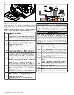
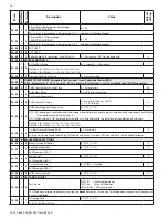
Figur
e 1 -
Thr
ee (3) C
asc
aded B
oilers with Upstr
eam or Do
wnstr
eam I
ndir
ec
t W
at
er H
ea
ter - P
iping and
W
iring f
or EL
U-85WBN, EL
U-120WBN, EL
U-120W
CN, EL
U-150W
CN M
odels ONL
Y
S
TS
TS
TS
S
BUS
T B
120V
TT2
120V
OD
5V IN
120V
TNK
120V
SYS
120V
TT1
120V
PCB / CONTROL PANEL
BUS
T B
120V
TT2
120V
OD
5V IN
120V
TNK
120V
SYS
120V
TT1
120V
PCB / CONTROL PANEL
DHW
PUMP
CH
PUMP
120VAC JUNCTION BOX
DHW
PUMP
CH
PUMP
120VAC JUNCTION BOX
BUS
T B
120V
TT2
120V
OD
5V IN
120V
TNK
120V
SYS
120V
TT1
120V
PCB / CONTROL PANEL
RT
DHW
PUMP
CH
PUMP
120VAC JUNCTION BOX
OD
OD
MASTER
FOLLOWER
RT
FOLLOWER
DOWNSTREAM
INDIRECT FIRED
WATER HEATER
UPSTREAM
INDIRECT FIRED
WATER HEATER
Piping f
or M
odels:
EL
U-85WBN, 120WBN, 120WCN, 150WCN
N
O
TICE
In this plumbing applica
tion, par
amet
er 25.1.6 needs t
o be adjust
ed t
o setting 1.
This ensur
es the CH pump will not oper
ate dur
ing DHW demands
.
Follo
w the Establishing B
oilers as M
ast
er and F
ollo
w
ers instruc
tions when
connec
ting t
o the BUS t
er
minals
. C
onnec
ting t
o the BUS t
er
minals without
follo
wing these instruc
tions c
ould damage the main PCB
.