background image


THT45W-THT46 


EN - 28

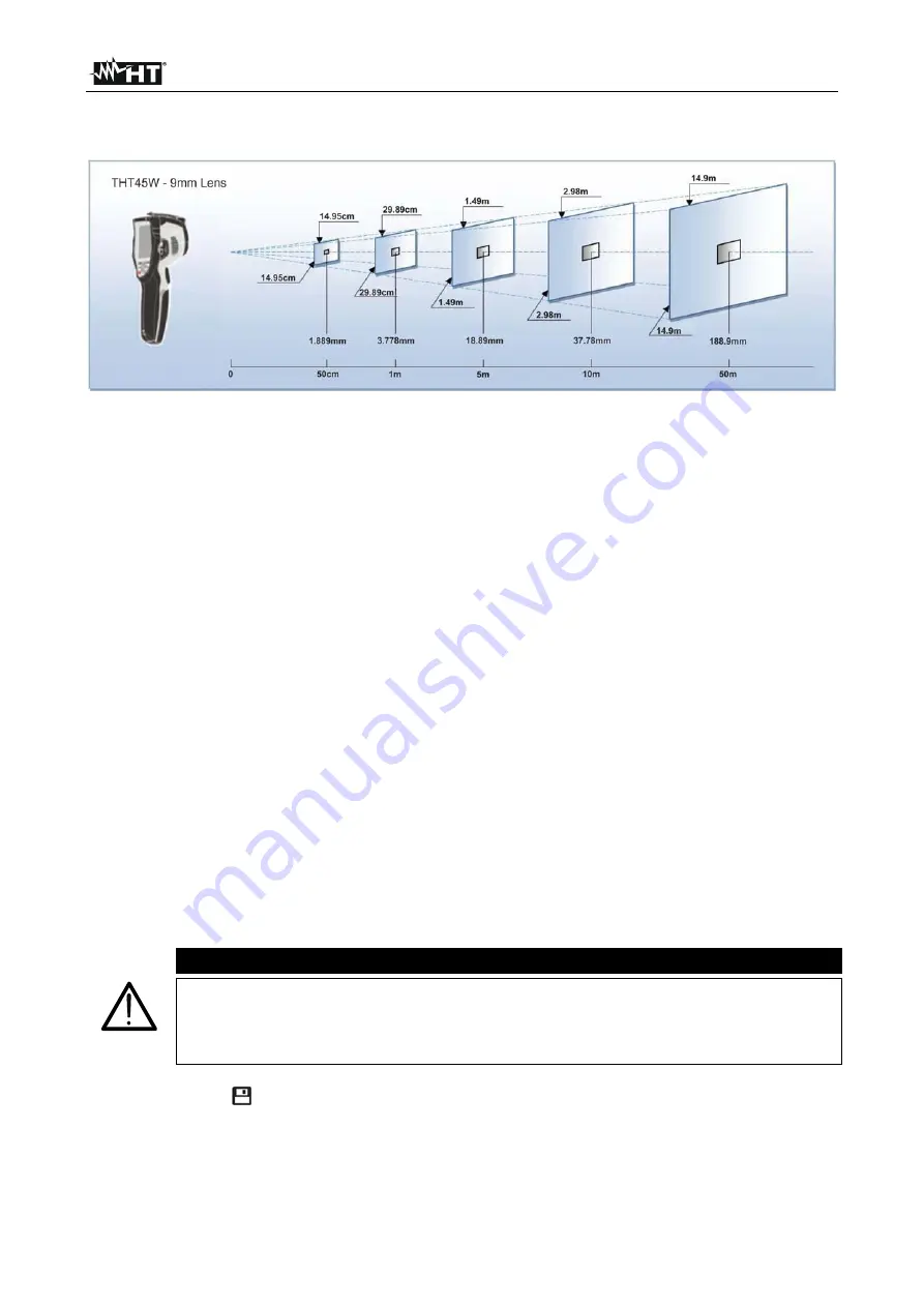
The representation of the ratio D (distance from the object) / S (surface of the object) for 
an instrument THT45W provided with 9mm lens is described below. 


Fig. 34: Representation of the THT45W instrument’s D/S ratio 


In the representation, it is possible to see how the IFOV (Instant Field Of View = 
geometrical resolution of the instrument = size of the single pxl of the IR sensor) is equal 
to 3.78mm at a distance of 1m of the instrument from the object being measured. This 
means that the instrument is capable of carrying out correct temperature measurements at 
a distance of 1m on objects with a size not lower than 3.78mm. 
 
5.  The typical application of thermal cameras is the one in which it is necessary to detect 

a temperature difference between two adjacent objects, as this kind of analysis is often 
sufficient to identify anomalies in electrical and mechanical appliances, etc. In such 
situations, in which an accurate temperature measurement is not strictly necessary, 
emissivity value may be set to “1” (see § 5.2.3), it is not necessary to consider the 
objects surface, its distance and the field of view). However, if accurate measures are 
required (e.g. the temperature of an electric motor), it is necessary to correctly set the 
parameters previously described in this manual.  

6.  Correctly set the temperature range of the image (see § 5.2.1), defining the adequate 

values according to the MIN and MAX temperatures detected within the measured 
area. 

7. Frame the objects to be measured by using the laser pointer, if necessary (see § 

4.2.4). The instrument displays the temperature values associated with the measuring 
cursors. 

8. Use the 

T

 (Trigger) key to freeze the image on the display and save it on the external 

micro SD card. The instrument saves the images in sequence with file name 
“YYYYMMDD_xxxx.jpg” 


CAUTION 


In the IR and Visible image visualization modes (see § 5.2.4). during the 
image saving operation 

waiting at least 1s

 after the pressing of “Save” key 

before move the camera from the object in front of it in order to avoid the 
possible mismatch of IR and visible images inside the gallery section 

 
9.  Press the key 

 to see the saved images again (see § 5.5). 


Summary of Contents for THT45W

Page 1: ...Copyright HT ITALIA 2018 Version EN 2 02 17 05 2018 ENGLISH User manual...

Page 2: ...AUF 21 5 2 5 Palette Menu 22 5 2 6 Range Menu 22 5 2 7 Image adjustment 23 5 3 Saving the image on the display 24 5 4 Recording a video on the display 24 5 5 Recalling and deleting displayed images a...

Page 3: ...hey must be used only if in good conditions and replaced with identical models when necessary Check that the battery is correctly inserted Check that the LCD display gives indications consistent with...

Page 4: ...ld spots of the image Storage of JPG images on external micro SD card IR sensor resolution 80x80pxl THT45W 160x120pxl THT46 USB port for PC connection and image transfer WiFi feature for connection wi...

Page 5: ...ing contains all components indicated in 8 5 In case of discrepancy please contact the Dealer In case the instrument should be replaced please carefully follow the instructions given in 10 3 2 INSTRUM...

Page 6: ...ent s front and backside CAPTION 1 LCD display 2 Function keys 3 Holes for non slip strap 4 Lens protection cap 5 In built visual photo camera 6 Laser pointer 7 Built in illuminator 8 Lens associated...

Page 7: ...4 Instrument s inputs and outputs location Fig 3 Description of the instrument s inputs and outputs CAPTION 15 Battery charge indicator LED 16 Input for connecting AC adapter battery charger and micro...

Page 8: ...THT45W THT46 EN 7 Fig 4 Description of the instrument s battery compartment CAPTION 1 Inside of the battery compartment 2 Battery insertion section...

Page 9: ...ers 4 2 3 Key Pressing and hold the key allows activating deactivating the internal illuminator see Fig 1 Part 6 The same key is also used for the selection of system parameters 4 2 4 Key Pressing and...

Page 10: ...centage x1 x32 Battery charge level indication see 8 2 Indication of active WiFi connection only THT45W 17 28 Indication of the system s current time Level Indication of temperature levels of the IR i...

Page 11: ...the original image 5 1 3 Adjusting the distance of the object in Fusion screens In Fusion display mode see 5 2 4 due to the different position of the lens and of the built in photo camera when the obj...

Page 12: ...defines the selection of the cursors which can be used while measuring max 3 cursors Emiss menu defines the setting of the emissivity of the object Image menu defines the display modes of the image Pa...

Page 13: ...uage setting 2 Use the or keys to select the desired language among the ones available 3 Press the key Select to confirm or Close to exit without saving Section Temp Unit In this section it is possibl...

Page 14: ...tions on the instrument 2 Press the key Select to restore the default conditions see Table 1 or Close to cancel the operation Parameter Default setting Cursor in the middle of the display On Max tempe...

Page 15: ...sired values of date and time 4 Press the key Ok to confirm or Cancel to exit without saving Information section This section contains general information about the instrument 1 Select the item Inform...

Page 16: ...e among the options 0 5m 1m 1 5m or 2m 3 Press the key Select to confirm or Close to exit without saving Auto power off section In this section it is possible to enable disable and adjust the auto pow...

Page 17: ...3 Press the key Select to confirm or Close to exit without saving WiFi section only THT45W In this section it is possible to enable disable the WiFi feature for the connection of the instrument to mo...

Page 18: ...he item Measurement with the keys or and press the key The screen Fig 17 Right side is shown on the display Fig 17 Setting of measuring cursors 2 Use the keys or and press and hold the key Select or t...

Page 19: ...ter 0 96 Stainless steel 0 14 Aluminium foil 0 09 Asphalt 0 96 Cement 0 97 Cast iron 0 81 Rubber 0 95 Wood 0 85 Bricks 0 75 Tape 0 96 Brass foil 0 06 Human skin 0 98 PVC plastic 0 93 Polycarbonate 0 8...

Page 20: ...rm your custom setting of the emissivity value with the Select key Use the keys or to set the value in the range 0 01 1 00 5 Press the Close key to confirm your setting and to go back to the initial s...

Page 21: ...Use the keys or to select the desired display mode among the options IR infrared image Visual visual image MIX fusion of IR image into the visual one see Fig 21 and AUF Auto Fusion function see 5 2 4...

Page 22: ...c or Manual image adjustment see 5 2 7 Automatic adjustment Fig 22 Visualization of image with AUF function in Automatic adjustment Manual adjustment With instrument in Manual adjustment mode symbol a...

Page 23: ...Press the Select key or the key to confirm the operation and go back to the previous screen of the Close key to exit without any modification 5 2 6 Range Menu In this section it is possible to define...

Page 24: ...e desired value of the temperature associated to the maximum level Press and hold the keys for a quick setting of the value 5 Press the Ok key to confirm The values of the set levels are maintained by...

Page 25: ...ving the image on the display 5 Press the Cancel key to exit without saving 5 4 RECORDING A VIDEO ON THE DISPLAY 1 Insert the micro SD card into the relevant slot of the instrument see Fig 4 The icon...

Page 26: ...he key Browse to access the gallery of saved images videos see Fig 29 Left side 4 Press the key Open to recall the selected image video on the display 5 Press the Option key The following screen appea...

Page 27: ...the jack of the headphones into the instrument see Fig 2 Part 17 3 Adjust the level of sound volume see 5 2 1 4 Press the T Trigger key to activate video playback A cursor and progress bar are shown o...

Page 28: ...tarts when the instrument is switched on and continues during the thermal cameras normal operation during which the image freezes for a few seconds in order to eliminate offset errors The noise produc...

Page 29: ...cessary emissivity value may be set to 1 see 5 2 3 it is not necessary to consider the objects surface its distance and the field of view However if accurate measures are required e g the temperature...

Page 30: ...3 Part 16 and to the PC The following screen see Fig 35 Left side is shown on the display Fig 35 Transferring images videos onto the PC 4 Use the keys or to select the option PC Transfer and press th...

Page 31: ...age on the instrument s display in real time 4 Disconnect the USB cable to go back to the instrument s main screen 5 8 HDMI VIDEO OUTPUT The video output available in the instrument see Fig 2 Part 18...

Page 32: ...l time of color palettes Saving snapshots within the mobile device Download images from instrument with USB OTG cable connection Creation of reports in PDF format Sharing images snapshots reports via...

Page 33: ...mage Visualization of Fusion image see 5 2 4 Visualization of Auto Fusion image AUF see 5 2 4 1 Selection of Iron palette Selection of Rainbow palette Selection of Grey scale palette Selection of Reve...

Page 34: ...USB mode 2 Copy of IR images from PC or micro SD card Fig 39 Visualization of images gallery Analysis and sharing IR images 1 Touch the menu icon and select the Library option in order to open the ga...

Page 35: ...previous menu Function Description Allows to view the properties of the open image name size instrument model Allows to delete the open image Allows to define the name of the report related to the op...

Page 36: ...THT45W THT46 EN 35 Funcion Description Allows you to select the type of image report sharing program saved on the mobile device e mail social networks cloud etc Fig 43 Shared of images report...

Page 37: ...CD ROM into the reader of the PC 2 Launch the file THTLink exe found inside the CD ROM and follow the guided installation procedure 7 3 MAIN CHARACTERISTICS OF THE THTLINK SOFTWARE With launched progr...

Page 38: ...ay in a range between 0 C and 50 C 32 F and 122 F When using the instrument for the first time recharge the battery for at least 6 hours 1 Connect the battery charger provided with the instrument to t...

Page 39: ...Li ION battery 3 7V 2000mAh AC DC 100 240V 5V adapter universal plugs Micro SD card 8GB USB cable USB OTG cable HDMI video cable Set of headphones for intercom Non slip strap CD ROM with Windows softw...

Page 40: ...sors 3 Fixed Max Temp Min Temp Inbuilt photo camera 1 3Mpxl FOV 59 PiP fusion function IR in Visual and AUF function Video output HDMI IR video recording micro SD card MP4 1280x960 30fps max 60min Mem...

Page 41: ...a consequence of improper packaging Repairs which may become necessary as a consequence of interventions performed by unauthorized personnel Modifications to the instrument performed without the manuf...

Reviews: