


distributed by
Assembly and alignment
FM 239 MuW Beta-Typ-Z Rev.01
2018-06-19
19
Proceed as follows
1.
Place the motor and the coupling elements in the mounting position
alongside the linear unit.
2.
Check the direction of rotation of the motor. It must correspond to
the safety limit switches (Figure 6). Change the direction of rotation
of the motor if required.
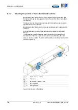
3.
If the coupling diameter is smaller than the D measurement at the
motor mounting (4), first mount the coupling half 1 (1) (bore flush
with the drive shaft) and then the motor mounting (4) (Figure 7).
If the coupling diameter is larger than the D measurement at the
motor mounting (4), first mount the motor mounting (4) and then the
coupling half 1 (1) (bore flush with the drive shaft). Tighten the
coupling clamping screw using the mounting bore on the motor
mounting (4).
4.
If necessary, push the coupling collar (2) onto the coupling.
5.
Fix the coupling half 2 (3) to the motor journal.
6.
Attach the motor to the motor mounting.
Summary of Contents for Beta 110-ZSE
Page 2: ......