background image


27 

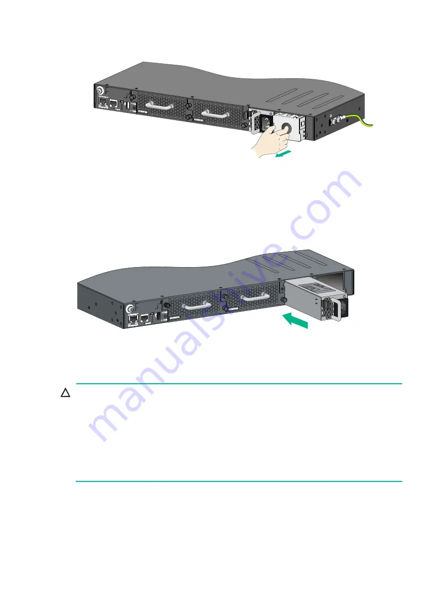
Figure 33 Removing the filler panel from a power module slot 


3. 

Unpack the power supply and verify that the power supply model is correct. 

4. 

Correctly orient the power supply with the power supply slot (see 

Figure 34

), grasp the handle 

of the power supply with one hand and support its bottom with the other, and slide the power 
supply slowly along the guide rails into the slot. 
The slot is foolproof. If you cannot insert the power supply into the slot, re-orient the power 
supply rather than use excessive force to push it in. 

Figure 34 Installing a power supply 


Removing a power supply 


CAUTION: 


When an HPE 5940 48SFP+ 6QSFP28, HPE 5940 48XGT 6QSFP28, HPE 5940 48XGT 6QSFP+, HPE 
5940 48SFP+ 6QSFP+, HPE 5940 , or HPE 5940 2-slot switch has two power supplies in 1+1 
redundancy mode, removing one power supply does not affect the operation of the switch. When the 
switch has only one power supply installed, removing the power supply powers off the switch. 


When an HPE 5940 4-slot switch has four power modules in 2+2 redundancy mode, removing one or two 
power modules does not affect the operation of the switch. When the switch has only two power module 
installed, removing a power module might power off the switch or cause power insufficiency. 


The power cord color code scheme in 

Figure 35

 is for illustration only. The cable delivered for your country 

or region might use a different color scheme. When you connect the power cord, always identify the 
polarity symbol on its wires. 


The power supply removing procedures are the same for all HPE FlexFabric 5940 switches. This 
section uses the HPE 5940  switch as an example: 

To remove a power supply: 

1. 

Wear an ESD wrist strap and make sure it makes good skin contact and is reliably grounded. 

2. 

Squeeze the tabs on the power cord connector with your thumb and forefinger, and pull the 
connector out to remove the power cord, as shown in 

Figure 35

Summary of Contents for FlexFabric 5940 SERIES

Page 1: ...HPE FlexFabric 5940 Switch Series Installation Guide Part number 5200 2842b Document version 6W105 20171215 ...

Page 2: ...tware Computer Software Documentation and Technical Data for Commercial Items are licensed to the U S Government under vendor s standard commercial license Links to third party websites take you outside the Hewlett Packard Enterprise website Hewlett Packard Enterprise has no control over and is not responsible for information outside the Hewlett Packard Enterprise website Acknowledgments Intel Ita...

Page 3: ... Connecting the power cord 29 Connecting an AC power cord 29 Connecting a DC power cord 29 Installing removing an interface module 30 Installing an interface module 30 Removing an interface module 32 Verifying the installation 32 Accessing the switch for the first time 33 Setting up the configuration environment 33 Connecting the console cable 33 Serial console cable 33 USB mini console cable 34 C...

Page 4: ...ies 59 Fan trays 60 Interface modules 61 Appendix C Ports and LEDs 64 Ports 64 Console port 64 Management Ethernet port 64 USB port 65 SFP port 66 QSFP port 68 QSFP28 port 71 1 10GBASE T autosensing Ethernet port 74 LEDs 74 System status LED 74 SFP port LED 74 QSFP port LED 75 QSFP28 port LED 75 Management Ethernet port LEDs 76 1 10GBASE T autosensing Ethernet port LEDs 76 Fan tray alarm LEDs 77 A...

Page 5: ...G900A HPE A58x0AF 300W AC Power Supply 300W AC JG901A HPE A58x0AF 300W DC Power Supply 300W DC Fan trays JC682A HPE 58x0AF Back Power Side to Front Port Side Airflow Fan Tray LSWM1FANSC JC683A HPE 58x0AF Front Port Side to Back Power Side Airflow Fan Tray LSWM1FANSCB JG552A HPE X711 Front Port Side to Back Power Side Airflow High Volume Fan Tray LSWM1HFANSCB JG553A HPE X712 Back Power Side to Fron...

Page 6: ...the chassis while the switch is operating or when the switch is just powered off When replacing FRUs including power supplies interface modules and fan trays wear an ESD wrist strap to avoid damaging the units Examining the installation site The HPE FlexFabric 5940 switches must be used indoors Mount your switch in a rack and verify the following items Adequate clearance is reserved at the air inl...

Page 7: ...m must also meet strict limits on salts acids and sulfides to eliminate corrosion and premature aging of components as shown in Table 3 Table 3 Harmful gas limits in the equipment room Gas Maximum concentration mg m3 SO2 0 2 H2S 0 006 NH3 0 05 Cl2 0 01 EMI All electromagnetic interference EMI sources from outside or inside of the switch and application system adversely affect the switch in the fol...

Page 8: ...he following tools yourself Phillips screwdriver ESD wrist strap Marker Installation accessories Table 4 Installation accessories Product code Description Quantity Applicable models 5066 0850 1 U mounting bracket kit including one pair of mounting brackets and eight M4 countersunk screws 1 kit All HPE FlexFabric 5940 switches 5190 0719 Mounting brackets for the HPE 5940 2 slot switch 1 kit HPE 594...

Page 9: ...cluding one pair of slide rails and four M4 countersunk screws 1 kit HPE 5940 48SFP 6QSFP28 HPE 5940 48SFP 6QSFP 5184 6723 Grounding cable 1 All HPE FlexFabric 5940 switches 5185 9579 Grounding screw 2 All HPE FlexFabric 5940 switches 5003 2403 Interface module filler module 1 HPE 5940 2 slot HPE 5940 4 slot 5190 1773 Power supply filler panel 1 All HPE FlexFabric 5940 switches 5185 8688 5400 0249...

Page 10: ...ct code Description Quantity Applicable models 5185 8748 Removable cable tie 1 All power supplies 5185 8627 Console cable 1 All HPE FlexFabric 5940 switches 5187 9022 QSFP dust plug As required HPE 5940 32QSFP ...

Page 11: ...on a mounting screw on the chassis cover intact and if you want to open the chassis contact Hewlett Packard Enterprise for permission Otherwise Hewlett Packard Enterprise shall not be liable for any consequence caused thereby Figure 1 Hardware installation flow ...

Page 12: ...E 5940 48XGT 6QSFP HPE 5940 48XGT 6QSFP28 1U high one pair See Figure 2 N A 1U high including one pair of chassis rails and one pair of slide rails See Figure 5 HPE 5940 48SFP 6QSFP HPE 5940 48SFP 6QSFP28 1U high one pair See Figure 2 N A 1U high including one pair of chassis rails and one pair of long slide rails See Figure 7 HPE 5940 2 slot 1U high one pair See Figure 3 N A 1U high including one...

Page 13: ...brackets for the HPE 5940 2 slot switch Figure 4 Mounting brackets for the HPE 5940 4 slot Switch 1 Cable management bracket 2 Mounting bracket Figure 5 1U chassis rail and short slide rail 1 Chassis rail 2 Slide rail 1 2 ...

Page 14: ...s available you can put the switch on the rack shelf slide the switch to an appropriate location and attach the switch to the rack with the mounting brackets Follow these guidelines when you install the switch in a 19 inch rack The distance between the front and rear posts of the rack must meet the requirements described in Table 6 To secure the switch to the rack you must install not only mountin...

Page 15: ...XGT 6QSFP28 Using mounting brackets and short slide rails provided 405 mm 15 94 in 834 mm 32 83 in HPE 5940 2 slot Using mounting brackets and slide rails provided 520 mm 20 47 in 769 mm 30 28 in HPE 5940 4 slot Using mounting brackets and slide rails provided 518 mm 20 39 in 858 mm 33 78 in Attaching the mounting brackets chassis rails and grounding cable to the chassis The switch has one mountin...

Page 16: ...ition 3 Primary grounding point 4 Auxiliary grounding point 1 5 Network port side mounting position Figure 10 Mounting and grounding positions on the HPE 5940 48SFP 6QSFP switch 1 Auxiliary grounding point 2 2 Power supply side mounting position 3 Primary grounding point 4 Auxiliary grounding point 1 5 Network port side mounting position ...

Page 17: ... the mounting brackets are in the power supply side mounting position align the chassis rails with the screw holes at the front of the side panels see Figure 12 Figure 14 and Figure 16 If the mounting brackets are in the network port side mounting position align the chassis rails with the screw holes at the rear of the side panels see Figure 13 Figure 15 and Figure 17 3 Use M4 screws provided to a...

Page 18: ... for the mounting brackets Figure 13 Attaching the mounting brackets and chassis rails to the HPE 5940 32QSFP switch network port side mounting position for the mounting brackets Figure 14 Attaching the mounting brackets and chassis rails to the HPE 5940 2 slot switch power supply side mounting position for the mounting brackets ...

Page 19: ... for the mounting brackets Figure 16 Attaching the mounting brackets and chassis rails to the HPE 5940 4 slot switch power supply side mounting position for the mounting brackets Figure 17 Attaching the mounting brackets and chassis rails to the HPE 5940 4 slot switch network port side mounting position for the mounting brackets ...

Page 20: ...nnecting to the primary grounding point or auxiliary grounding point 1 3 Align the two hole grounding lug at one end of the cable with the grounding holes of the grounding point insert the grounding screws into the holes and tighten the screws with a screwdriver as shown in Figure 18 Figure 18 Attaching the grounding cable to the primary grounding point on the HPE 5940 32QSFP switch Attaching the ...

Page 21: ...de rails 5 One person performs the following operations a Supporting the bottom of the switch aligns the chassis rails with the slide rails on the rack posts b Pushes the switch slowly to slide the chassis rails along the slide rails until the mounting brackets are flush with the rack posts 6 Another person uses screws user supplied to attach the mounting brackets to the rack To secure the switch ...

Page 22: ... HPE 5940 48XGT 6QSFP switch in the rack power supply side mounting position for the mounting brackets Figure 21 Mounting the HPE 5940 48XGT 6QSFP switch in the rack network port side mounting position for the mounting brackets ...

Page 23: ...g the HPE 5940 2 slot switch in the rack power module side mounting position for the mounting brackets Figure 23 Mounting the HPE 5940 2 slot switch in the rack network port side mounting position for the mounting brackets ...

Page 24: ...ng position for the mounting brackets NOTE To rack mount the HPE 5940 4 slot switch by using 2U high mounting brackets and slide rails use two screws and two cage nuts to attach each mounting bracket to the rack Determine the screw installation positions based on the distances between the square holes on the rack posts The screw installation positions in Figure 24 and Figure 25 are for illustratio...

Page 25: ... and grounding terminals in this section are for illustration only Grounding the switch with a grounding strip WARNING Connect the grounding cable to the grounding system in the equipment room Do not connect it to a fire main or lightning rod If a grounding strip is available at the installation site connect the grounding cable to the grounding strip To connect the grounding cable 1 Attach the two...

Page 26: ...ethod is the same as connecting to the other two grounding points Grounding the switch by using the AC power cord If the installation site has no grounding strips you can ground an AC powered switch through the protective earth PE wire of the power cord but must make sure The power cord has a PE terminal The ground contact in the power outlet is securely connected to the ground in the power distri...

Page 27: ...switch Do not keep operating the system with one failed fan tray Make sure all slots have a module or filler panel installed when the switch is operating When two fan trays fail during switch operation For an HPE 5940 32QSFP or HPE 5940 2 slot switch finish replacing the fan trays within 2 minutes For an HPE 5940 48SFP 6QSFP HPE 5940 48XGT 6QSFP HPE 5940 48SFP 6QSFP28 HPE 5940 48XGT 6QSFP28 or HPE...

Page 28: ...tray with a Philips screwdriver until the fan tray is securely attached in the chassis see callout 2 in Figure 28 If the captive screw cannot be tightly fastened verify the installation of the fan tray Figure 28 Installing an LSWM1HFANSC fan tray for an HPE 5940 32QSFP switch Installing an LSWM1BFANSC LSWM1BFANSCB fan tray 1 Wear an ESD wrist strap and make sure it makes good skin contact and is r...

Page 29: ...act and is reliably grounded 2 Loosen the captive screw of the fan tray with a Philips screwdriver until it is fully disengaged from the switch chassis 3 Grasp the handle of the fan tray with one hand and pull the fan tray part way out of the slot Support the fan tray bottom with the other hand and pull the fan tray slowly along the guide rails out of the slot 4 Place the removed fan tray in an an...

Page 30: ...val procedure Installing a power supply CAUTION Follow the forward inertia of the power supply when inserting it into the chassis and make sure the power supply has firm contact with the connectors on the backplane To prevent damage to the connectors inside the switch chassis insert the power supply gently If you encounter a hard resistance while inserting the power supply pull out the power suppl...

Page 31: ...witch When the switch has only one power supply installed removing the power supply powers off the switch When an HPE 5940 4 slot switch has four power modules in 2 2 redundancy mode removing one or two power modules does not affect the operation of the switch When the switch has only two power module installed removing a power module might power off the switch or cause power insufficiency The pow...

Page 32: ...er supply bottom with one hand slowly pull the power supply out with the other hand 5 Put away the removed power supply in an antistatic bag for future use Figure 35 Removing the DC power cord 1 Press the tabs on the power cord connector with your thumb and forefinger 2 Pull the power cord connector out Figure 36 Removing the power supply 1 Pivot the latch to the right with your thumb 2 Pull the p...

Page 33: ... the power cord to the handle of the power supply Connecting a DC power cord CAUTION The power cord color code scheme in Figure 38 is for illustration only The cable delivered for your country or region might use a different color scheme When you connect the power cord always identify the polarity symbol on its wires To connect a DC power cord 1 Unpack the DC power cord identify the plug for conne...

Page 34: ...terface module slots For the available interface modules see Appendix B FRUs and compatibility matrixes The interface module installation and removal procedures are the same This section uses the LSWM18QC interface module as an example Installing an interface module 1 Wear an ESD wrist strap and make sure the wrist strap makes good skin contact and is reliably grounded 2 Optional If the target int...

Page 35: ...r lever 2 Latch 4 Press the latch on the interface module to release the ejector lever 5 Insert the interface module slowly into the slot along the guide rails as shown by callout 1 in Figure 41 6 Rotate inward the ejector lever as shown by callout 2 in Figure 41 until the latch locks the ejector lever in place Figure 41 Installing an LSWM18QC interface module 1 2 ...

Page 36: ...ector lever as shown by callout 1 in Figure 42 5 Pull out the interface module slowly out of the interface module slot as shown by callout 2 in Figure 42 6 Place the removed interface module in the anti static bag Figure 42 Removing an LSWM18QC interface module Verifying the installation After you complete the installation verify that There is enough space for heat dissipation around the switch an...

Page 37: ... use the two ways together on the same switch The example uses a console cable to connect a console terminal PC to the serial console port on the switch Figure 43 Connecting the serial console port to a terminal Connecting the console cable Serial console cable A serial console cable is an 8 core cable with a crimped RJ 45 connector at one end for connecting to the serial console port of the switc...

Page 38: ...sure you are connecting to the correct port The serial ports on PCs do not support hot swapping If the switch has been powered on connect the serial console cable to the PC before connecting to the switch and when you disconnect the cable first disconnect from the switch To connect to the configuration terminal through the USB mini console cable 1 Connect the standard USB Type A connector to the U...

Page 39: ...35 Figure 45 Device Driver Installation Wizard 6 Click Continue Anyway if the following dialog box appears Figure 46 Software Installation 7 Click Finish ...

Page 40: ...minal emulator programs see the user guides for these programs The following are the required terminal settings Bits per second 9600 Data bits 8 Stop bits 1 Parity None Flow control None Powering on the switch Before powering on the switch verify that the following conditions are met The power cord is correctly connected The input power voltage meets the requirement of the switch The console cable...

Page 41: ...iffer with software versions For more information about Boot ROM menu options see the software matching release notes for the device After the startup completes you can access the CLI to configure the switch For more information about the configuration commands and CLI see HPE FlexFabric 5940 Switch Series Configuration Guides and HPE FlexFabric 5940 Switch Series Command References ...

Page 42: ...en two switches use the 10 GE 40 GE or 100 GE ports IRF fabric setup flowchart Figure 48 IRF fabric setup flowchart To set up an IRF fabric Step Description 1 Plan IRF fabric setup Plan the installation site and IRF fabric setup parameters Planning IRF fabric size and the installation site Identifying the master switch and planning IRF member IDs Planning IRF topology and connections Identifying p...

Page 43: ... all member switches Plan the installation site depending on your network solution as follows Place all IRF member switches in one rack for centralized high density access Distribute the IRF member switches in different racks to implement the top of rack ToR access solution for a data center As your business grows you can plug HPE FlexFabric 5940 switches into the IRF fabric to increase the switch...

Page 44: ...he connections between IRF member switches Each IRF member switch has two IRF ports IRF port 1 and IRF port 2 To use an IRF port you must bind at least one physical port to it When connecting two neighboring IRF member switches you must connect the physical ports of IRF port 1 on one switch to the physical ports of IRF port 2 on the other switch The IRF port connections in the two figures are for ...

Page 45: ...r QSFP28 ports on the LSWM18CQMSEC interface module JH957A Planning the cabling scheme You can use twisted pair cables SFP QSFP QSFP28 cables or SFP QSFP QSFP28 transceiver modules and optical fibers to connect the switches for IRF connections If the IRF member switches are far away from one another choose the SFP QSFP QSFP28 transceiver modules and optical fibers If the IRF member switches are al...

Page 46: ...de to configure their member IDs member priorities and IRF port bindings Follow these guidelines when you configure the switches Assign the master switch higher member priority than any other switch Bind physical ports to IRF port 1 on one switch and to IRF port 2 on the other switch You perform IRF port binding before or after connecting IRF physical ports depending on the software release Execut...

Page 47: ...e HPE FlexFabric 5940 Switch Series Fundamentals Configuration Guide 4 Verify that you can manage all member switches as if they were one node 5 Display the running status of the IRF fabric by using the commands in Table 8 Table 8 Displaying and maintaining IRF configuration and running status Task Command Display information about the IRF fabric display irf Display all members IRF configurations ...

Page 48: ... the switch is steady red and the system outputs an alarm message that indicates a fan tray failure Solution See Installing removing a fan tray to replace the failed fan tray If the issue persists contact Hewlett Packard Enterprise Support Follow these guidelines when you install or remove a fan tray Do not power on the switch when the switch has no fan trays installed You must install two fan tra...

Page 49: ... correctly 2 Verify that the console cable has been connected correctly and no fault occurs on the console cable 3 Verify that the following settings are configured for the terminal Baud rate 9600 Data bits 8 Stop bits 1 Parity None Flow control None 4 If the issue persists contact Hewlett Packard Enterprise Support Garbled display on the configuration terminal Symptom The configuration terminal d...

Page 50: ...PE 5940 32QSFP switch comes with the two power supply slots empty and a power supply filler panel as an accessory You can install one or two power supplies for the switch as needed In Figure 55 two 650W AC power supplies are installed in the power supply slots For more information about installing and removing power supplies see Installing removing a power supply The HPE 5940 32QSFP switch comes w...

Page 51: ...PE 5940 48SFP 6QSFP switch comes with the two power supply slots empty and a power supply filler panel as an accessory You can install one or two power supplies for the switch as needed In Figure 58 two 300W AC power supplies are installed in the power supply slots For more information about installing and removing power supplies see Installing removing a power supply The HPE 5940 48SFP 6QSFP swit...

Page 52: ...Ethernet port 10 USB port The HPE 5940 48XGT 6QSFP switch comes with the two power supply slots empty and a power supply filler panel as an accessory You can install one or two power supplies for the switch as needed In Figure 61 two 650W AC power supplies are installed in the power supply slots For more information about installing and removing power supplies see Installing removing a power suppl...

Page 53: ...ment Ethernet port The HPE 5940 48SFP 6QSFP28 switch comes with the two power supply slots empty and a power supply filler panel as an accessory You can install one or two power supplies for the switch as needed In Figure 64 two 300W AC power supplies are installed in the power supply slots For more information about installing and removing power supplies see Installing removing a power supply The...

Page 54: ...NK ACT LED for the fiber management Ethernet port The HPE 5940 48XGT 6QSFP28 switch comes with the two power supply slots empty and a power supply filler panel as an accessory You can install one or two power supplies for the switch as needed In Figure 67 two 650W AC power supplies are installed in the power supply slots For more information about installing and removing power supplies see Install...

Page 55: ... and interface module 2 installed with a filler panel You can install one or two interface modules for the switch as needed In Figure 69 two LSWM18QC interface modules are installed in the interface module slots For more information about installing and removing interface modules see Installing removing an interface module The HPE 5940 2 slot switch comes with the two power supply slots empty and ...

Page 56: ...NSC fan trays are installed in the fan tray slots For more information about installing and removing fan trays see Installing removing a fan tray Figure 71 Left side panel 1 Primary grounding point 2 Auxiliary grounding point 1 HPE FlexFabric 5940 4 slot Figure 72 Front panel 1 Interface module 1 2 Interface module 2 3 Interface module 4 4 Interface module 3 ...

Page 57: ...ng and removing interface modules see Installing removing an interface module The HPE 5940 4 slot switch comes with the four power supply slots empty and two filler panels as accessories You can install two to four power supplies for the switch as needed In Figure 73 four 650W AC power supplies are installed in the power supply slots For more information about installing and removing power supplie...

Page 58: ...90 VAC to 264 VAC 47 to 63 Hz DC input voltage Rated voltage 40 VDC to 60 VDC Max voltage 40 VDC to 72 VDC Minimum power consumption Single AC input 132 W Dual AC inputs 145 W Single DC input 128 W Dual DC inputs 142 W Single AC input 75 W Dual AC inputs 81 W Single DC input 72 W Dual DC inputs 80 W Single AC input 135 W Dual AC inputs 150 W Single DC input 132 W Dual DC inputs 142 W Maximum power...

Page 59: ... in Weight 10 kg 22 05 lb 13 kg 28 66 lb Console ports 1 mini USB console port 1 serial console port 1 mini USB console port 1 serial console port Management Ethernet ports 1 10M 100M 1000M Base T copper port 1 SFP port 1 10M 100M 1000M Base T copper port 1 SFP port USB ports 1 1 1 10GBASE T autosensing Ethernet ports N A 48 SFP ports 48 N A QSFP ports N A N A QSFP28 ports 6 6 Fan tray slots 2 2 P...

Page 60: ...ical specifications 3 Item HPE 5940 2 slot HPE 5940 4 slot Dimensions H W D 44 2 440 660 mm 1 74 17 32 25 98 in 88 1 440 660 mm 3 47 17 32 25 98 in Weight 16 kg 35 27 lb 27 kg 59 52 lb Console port 1 mini USB console port 1 serial console port 1 mini USB console port 1 serial console port Management Ethernet port 1 1 USB port 1 1 QSFP port 2 N A Interface module slot 2 4 Fan tray slot 2 2 Power su...

Page 61: ...837 W Quadruple AC inputs 856 W Dual DC inputs 823 W Triple DC inputs 825 W Quadruple DC inputs 828 W Chassis leakage current compliance UL60950 1 EN60950 1 IEC60950 1 GB4943 Melting current of power supply fuse 10 A 250 VAC 30 A 250 VDC Operating temperature 0 C to 45 C 32 F to 113 F Operating humidity 10 to 90 noncondensing Fire resistance compliance UL60950 1 EN60950 1 IEC60950 1 GB4943 ...

Page 62: ...es Yes Yes 300W AC No Yes No Yes No No No 300W DC No Yes No Yes No No No Fan trays LSWM1FANS C No Yes No Yes No No No LSWM1FANS CB No Yes No Yes No No No LSWM1HFAN SC Yes Yes Yes Yes Yes Yes No LSWM1HFAN SCB Yes Yes Yes Yes Yes Yes No LSWM1BFAN SC No No No No No No Yes LSWM1BFAN SCB No No No No No No Yes Interface modules LSWM18QC No No No No No Yes Yes LSWM18CQ MSEC No No No No No Yes Yes LSWM124...

Page 63: ...has power supplies in redundancy you can replace a power supply without powering off the switch Make sure the power supply to be replaced is powered off before you replace it Table 13 Power supply specifications Power supply Specifications Remarks 650W AC Rated input voltage 100 VAC to 240 VAC 50 Hz or 60 Hz Max input voltage 90 VAC to 264 VAC 47 Hz to 63 Hz Max output power 650 W For more informa...

Page 64: ...ow 70 CFM Airflow direction From the port side to the power supply side Input voltage 12 V Maximum power consumption 60 W Documentation reference HPE LSWM1HFANSC and LSWM1HFANSCB Fan Assemblies Installation LSWM1FANSC Fans Two 40 40 28 mm 1 57 1 57 1 10 in fans Fan speed 18500 R P M Max airflow 45 CFM Airflow direction From the power supply side to the port side Input voltage 12 V Maximum power co...

Page 65: ... W Documentation reference HPE LSWM1BFANSC LSWM1BFANSCB Fan Trays User Guide LSWM1BFANSCB Fans One 80 80 76 mm 3 14 3 14 2 99 in fan Fan speed 20000 R P M Max airflow 120 CFM Airflow direction From the port side to the power supply side Input voltage 12 V Maximum power consumption 57 W Documentation reference HPE LSWM1BFANSC LSWM1BFANSCB Fan Trays User Guide Interface modules An HPE 5940 2 slot sw...

Page 66: ...or the transceiver modules and cables available for the QSFP28 ports see QSFP28 port JH957A HPE FlexFabric 5950 8 port QSFP28 MACsec Module LSWM18CQMSEC 8 QSFP28 ports JH182A HPE 5930 24 port 10GBase T and 2 port QSFP with MacSec Module LSWM124XGT2Q 24 10 GE copper ports 2 QSFP ports JH181A HPE 5930 24 port SFP and 2 port QSFP with MacSec Module LSWM124XG2Q 24 SFP ports 2 QSFP ports JH180A HPE 593...

Page 67: ...940 2 slot switch If an interface module slot starts up with an LSWM12H2Q interface module installed you can hot swap only LSWM12H2Q interface modules in the slot If an interface module slot starts up empty or with a non LSWM12H2Q interface module installed you can hot swap only non LSWM12H2Q interface modules in the slot If you change the interface module type in a slot you need to reboot the swi...

Page 68: ...rt Mini USB console port Connector type RJ 45 USB mini Type B Compliant standard EIA TIA 232 USB 2 0 Transmission baud rate 9600 bps default to 115200 bps Services Provides connection to an ASCII terminal Provides connection to the serial port of a local or remote through a pair of modems PC running terminal emulation program Provides connection to an ASCII terminal Provides connection to the USB ...

Page 69: ...ct code HPE description Central wavelength nm Connector Fiber type and diameter µm Max transmission distance JD102B HPE X115 100M SFP LC FX Transceiver 1310 LC Multi mode 50 125 2 km 1 24 miles Multi mode 62 5 125 JD120B HPE X110 100M SFP LC LX Transceiver 1310 LC Single mode 9 125 15 km 9 32 miles JD090A HPE X110 100M SFP LC LH40 Transceiver 40 km 24 86 miles USB port The switch has one OHC compl...

Page 70: ...e and diameter µm Modal bandwidth MHz km Max transmissi on distance JD089B HPE X120 1G SFP RJ45 T Transceiver N A RJ 45 Category 5 twisted pair N A 100 m 328 08 ft JD118B HPE X120 1G SFP LC SX Transceiver 850 LC Multi mode 50 125 500 550 m 1804 46 ft 400 500 m 1640 42 ft Multi mode 62 5 125 200 275 m 902 23 ft 160 220 m 721 78 ft JD119B HPE X120 1G SFP LC LX Transceiver 1310 LC Single mode 9 125 N...

Page 71: ...de 50 125 500 380 m 1246 72 ft 2000 500 m 1640 42 ft JG880A HPE X190 8G 4G 2G SFP LC Long Wave Transceiver 1310 LC Single mode 9 125 N A 10 km 6 21 miles Table 23 SFP cables available for the SFP ports Product code HPE description Max transmission distance Data rate JD095C HPE X240 10G SFP SFP 0 65m DA Cable 0 65 m 2 13 ft 10 31 Gbps JD096C HPE X240 10G SFP SFP 1 2m DA Cable 1 2 m 3 94 ft 10 31 Gb...

Page 72: ...ansceiver modules SFP transceiver modules and SFP cables available for the SFP ports contact Hewlett Packard Enterprise Support or marketing staff For more information about HPE SFP transceiver modules SFP transceiver modules and SFP cables see HPE Comware Based Devices Transceiver Modules User Guide QSFP port The HPE 5940 32QSFP HPE 5940 48XGT 6QSFP and HPE 5940 48SFP 6QSFP switches provide fixed...

Page 73: ... 1331 LC Single mode 9 125 N A 10 km 6 21 miles JL286A HPE X140 40G QSFP LC LR4L 2km SM Transceiver Four lanes 1271 1291 1311 1331 LC Single mode 9 125 N A 2 km 1 24 miles Table 26 40G QSFP cables available for the QSFP ports Product Code HPE description Cable length JG326A HPE X240 40G QSFP QSFP 1m Direct Attach Copper Cable 1 m 3 28 ft JG327A HPE X240 40G QSFP QSFP 3m Direct Attach Copper Cable ...

Page 74: ...P to QSFP 7m Active Optical Cable 7 m 22 97 ft 40 Gbps JL288A HPE X2A0 40G QSFP to QSFP 10m Active Optical Cable 10 m 32 81 ft JL289A HPE X2A0 40G QSFP to QSFP 20m Active Optical Cable 20 m 65 62 ft Figure 77 QSFP cable 1 Connector 2 Pull latch Figure 78 QSFP to 4 x SFP cable 1 QSFP module 2 QSFP side pull latch 3 SFP side pull latch 4 SFP module ...

Page 75: ...ontact Hewlett Packard Enterprise Support or marketing staff You can use a QSFP 40G SR4 MM850 or QSFP 40G CSR4 MM850 transceiver module to connect a QSFP port to four SFP ports The QSFP transceiver module and SFP transceiver modules to be connected must be the same in specifications including central wavelength and fiber type For more information about HPE QSFP transceiver modules QSFP cables and ...

Page 76: ... Four lanes 1264 5 to 1277 5 1284 5 to 1297 5 1304 5 to 1317 5 1324 5 to 1337 5 LC Multi mode 9 125 N A 2 km 1 24 miles Table 30 QSFP28 copper cables available for the QSFP28 ports Product Code HPE description Cable length JL271A HPE X240 100G QSFP28 to QSFP28 1m Direct Attach Copper Cable 1 m 3 28 ft JL272A HPE X240 100G QSFP28 to QSFP28 3m Direct Attach Copper Cable 3 m 9 84 ft JL273A HPE X240 1...

Page 77: ... split into four 10GE ports The other QSFP28 ports on the switch do not support port splitting NOTE As a best practice use HPE QSFP QSFP28 transceiver modules and cables for the QSFP28 ports The available HPE QSFP QSFP28 transceiver modules and cables are subject to change over time For the most recent list of available HPE QSFP QSFP28 transceiver modules and cables contact Hewlett Packard Enterpr...

Page 78: ...ts on the distribution frame are preferably not adjacent for example If the device connects to one distribution frame connect port 1 on the device to port 1 on the distribution frame port 2 on the device to port 3 on the distribution frame and port 3 on the device to port 5 on the distribution frame If the device connects to two distribution frames connect port 1 on the device to port 1 on distrib...

Page 79: ...eady yellow A transceiver module or cable has been correctly installed The port has a link and is operating at 10 Gbps Flashing yellow The port is sending or receiving data at 10 Gbps Off No transceiver module or cable has been installed or no link is present on the port QSFP28 port LED For the description of the QSFP28 port LED on an LSWM18CQMSEC interface module see Table 35 For the LED descript...

Page 80: ...10 100 1000 Mbps and a link is present Flashing green The copper management Ethernet port is receiving or sending data Off The copper management Ethernet port is not connected Table 39 Description for the fiber management Ethernet port LED LED mark Status Description LINK ACT Off The fiber management Ethernet port is not connected Steady green The fiber management Ethernet port is operating at 100...

Page 81: ...EDs The LSWM1BFANSC and LSWM1BFANSCB fan trays provide an Alarm LED Table 41 LSWM1BFANSC and LSWM1BFANSCB fan tray alarm LED description Status Description On The fan tray is faulty Off The fan tray is operating correctly ...

Page 82: ...2 slot LSWM1HFANSC From the power supply side to the port side LSWM1HFANSCB From the port side to the power supply side HPE 5940 48SFP 6QSFP28 HPE 5940 48XGT 6QSFP28 LSWM1FANSC or LSWM1HFANSC From the power supply side to the port side LSWM1FANSCB or LSWM1HFANSCB From the port side to the power supply side HPE 5940 4 slot LSWM1BFANSC From the power supply side to the port side LSWM1BFANSCB From th...

Page 83: ...es separated by vertical bars from which you select at least one x y Asterisk marked square brackets enclose optional syntax choices separated by vertical bars from which you select one choice multiple choices or none 1 n The argument or keyword and argument combination before the ampersand sign can be entered 1 to n times A line that starts with a pound sign is comments GUI conventions Convention...

Page 84: ... a router that supports Layer 2 forwarding and other Layer 2 features Represents an access controller a unified wired WLAN module or the access controller engine on a unified wired WLAN switch Represents an access point Represents a wireless terminator unit Represents a wireless terminator Represents a mesh access point Represents omnidirectional signals Represents directional signals Represents a...

Page 85: ...rovide a mechanism for accessing software updates through the product interface Review your product documentation to identify the recommended software update method To download product updates go to either of the following Hewlett Packard Enterprise Support Center Get connected with updates page http www hpe com support e updates Software Depot website http www hpe com support softwaredepot To vie...

Page 86: ...pport selfrepair Insight Remote Support not applicable to all devices http www hpe com info insightremotesupport d ocs Customer self repair Hewlett Packard Enterprise customer self repair CSR programs allow you to repair your product If a CSR part needs to be replaced it will be shipped directly to you so that you can install it at your convenience Some parts do not qualify for CSR Your Hewlett Pa...

Page 87: ...y errors suggestions or comments to Documentation Feedback mailto docsfeedback hpe com When submitting your feedback include the document title part number edition and publication date located on the front cover of the document For online help content include the product name product version help edition and publication date located on the legal notices page ...

Page 88: ...ure 44 Fan trays 60 G Grounding the switch 21 I Installation accessories 4 Installation tools 4 Installing the switch in a 19 inch rack 8 Installing removing a fan tray 23 Installing removing a power supply 26 Installing removing an interface module 30 Interface modules 61 IRF fabric setup flowchart 38 L LEDs 74 N Network topology icons 80 P Planning IRF fabric setup 39 Ports 64 Power supplies 59 ...

Reviews: