HPE EDGELINE EL10, User Manual
The HPE Edgeline EL10 is a powerful edge computing device designed for industrial environments. Easily set up and optimize performance with the user manual available for free download from manualshive.com. Get detailed instructions and troubleshooting tips to maximize the potential of your device.
Share
Download


Reviews:
No comments
Related manuals for EDGELINE EL10

MG1
Brand: Pace Pages: 2

BS Series
Brand: Vega Pages: 39

NETWORK INTERFACE CARDS
Brand: Secure Computing Pages: 17

CPN-55-20
Brand: WITELCOM Pages: 2

P-660R-T Series
Brand: ZyXEL Communications Pages: 9
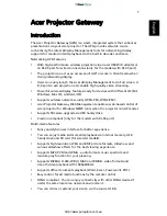
Projector Gateway
Brand: Acer Pages: 58

SpeedTouch 510
Brand: Technicolor - Thomson Pages: 21

UPS-GWS01
Brand: Aaeon Pages: 20

WG-2
Brand: FireAngel Pages: 8

PCT
Brand: peoplenet Pages: 19

EnOcean 02LINE
Brand: TRI02SYS Pages: 4

WSG-500
Brand: Planet Pages: 162

GWY-00
Brand: Renu Electronics Pages: 105

50.0070.0011.00
Brand: FP Pages: 82

E5810B
Brand: Agilent Technologies Pages: 157

SC2-A470M1
Brand: Sfere Pages: 16

G650
Brand: Avaya Pages: 298

W310
Brand: Avaya Pages: 440


