background image

Interconnect bay
labels

c3000 interconnect
bay

c7000 interconnect bay

Server blade signal

3 and 4

7 and 8

3 and 4

5 and 6

Mezzanine 3

3 and 4

7 and 8

For detailed port mapping information, see the BladeSystem enclosure installation
poster or the BladeSystem enclosure setup and installation guide for your product on
the Hewlett Packard Enterprise website (

http://www.hpe.com/info/bladesystem/

documentation

).

Installing the server blade into the enclosure

NOTE:

When installing additional blades into an enclosure, additional power supplies

might also be needed to meet power requirements. For more information, see the
BladeSystem enclosure setup and installation guide for your product on the Hewlett
Packard Enterprise website (

http://www.hpe.com/info/bladesystem/documentation

).

NOTE:

Before installing and initializing the server blade, install any server blade

options, such as an additional processor, hard drive, or mezzanine card.

1.

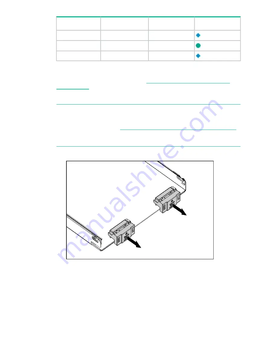
Remove the connector covers if they are present.

2.

Prepare the server blade for installation.

18

Summary of Contents for BL860c i2

Page 1: ...e BL860c i2 BL860c i4 BL870c i2 BL870c i4 BL890c i2 and BL890c i4 Abstract This document contains specific information that is intended for users of this Hewlett Packard Enterprise product Part Number...

Page 2: ...dard commercial license Links to third party websites take you outside the Hewlett Packard Enterprise website Hewlett Packard Enterprise has no control over and is not responsible for information outs...

Page 3: ...13 Removing a c7000 device bay divider 14 Removing a c3000 device bay mini divider or device bay divider 15 Installing interconnect modules 16 Interconnect bay numbering and device mapping 16 Installi...

Page 4: ...enclosures specifically the 10U c7000 and the 6U c3000 Enclosures The nPartition configuration feature is enabled from the factory enabling the BL870c i4 and BL890c i4 to be partitioned into one more...

Page 5: ...s Figure 1 i2 server blade components Figure 2 i4 server blade components 8 ICH mezzanine connector 1 CPU0 2 CPU0 power connector 9 Mezzanine connector 3 type 1 or 2 10 CPU1 power connector 3 Mezzanin...

Page 6: ...type 1 or 2 11 CPU1 12 SAS backplane 5 System board thumbscrew 13 Pull tab NOTE The iLO 3 password is located on the pull tab 6 i2 Battery CR2032 i4 System board thumbscrew 7 i2 System board thumbscr...

Page 7: ...cm 2 025 in Width 48 51 cm 19 1 in Depth Unloaded 8 6 kg 19 lb Weight Fully loaded 11 3 kg 25 lb Table 2 Blade Link dimensions and weight Weight Width Height Blade Link type 5 lb 22 kg 51 mm 2 in 44...

Page 8: ...rver Blade or HPE Integrity BL860c i4 Server Blade in the list of servers and then select the Generalized Site Preparation Guidelines Sample Site Inspection Checklist Table 3 Customer and Hewlett Pack...

Page 9: ...e for maintenance 13 Are AC outlets available for servicing needs for example laptop 14 Does the input voltage correspond to equipment specifications 15 Is dual source power used If so identify types...

Page 10: ...receive 12 volts directly from the enclosure The voltage is immediately passed through an E fuse circuit which will immediately cut power to the blade if a short circuit fault or over current conditio...

Page 11: ...essential factor of a successful server blade installation and includes the following tasks Gather LAN information Determine the two IP addresses for the iLO 3 MP LAN and the server blade LAN Establis...

Page 12: ...rrived NOTE To identify each item by part number see the sales order packing slip Returning damaged equipment If the equipment is damaged immediately contact your Hewlett Packard Enterprise customer s...

Page 13: ...lade 4 Configure iLO 3 MP access 5 Access iLO 3 MP 6 Access UEFI from iLO 3 MP 7 Download latest firmware and update using HP Smart Update Manager 8 Install and boot the OS 9 Installing and powering o...

Page 14: ...h the device bay shelf back until it stops lift the right side slightly to disengage the two tabs from the divider wall and then rotate the right edge downward clockwise 3 Lift the left side of the de...

Page 15: ...bay mini divider or device bay divider 1 Slide the locking tab down 2 Remove the mini divider or divider c3000 mini divider Push the divider toward the back of the enclosure until the divider drops o...

Page 16: ...age the tabs from the wall c Rotate the divider clockwise d Remove the divider from the enclosure Installing interconnect modules For specific steps to install interconnect modules see the documentati...

Page 17: ...rconnect module in the bay corresponding to the embedded NIC or mezzanine signals Interconnect bay labels c3000 interconnect bay c7000 interconnect bay Server blade signal 1 1 NIC 1 Embedded 1 2 NIC 2...

Page 18: ...lling the server blade into the enclosure NOTE When installing additional blades into an enclosure additional power supplies might also be needed to meet power requirements For more information see th...

Page 19: ...r blade power states The server blade has three power states standby power full power and off Install the server blade into the enclosure to achieve the standby power state Server blades are set to po...

Page 20: ...and programs Use one of the following methods to power off the server blade NOTE To power off blades in a conjoined configuration only power off the Monarch blade Use a virtual power button selection...

Page 21: ...3 TUI and enter the DF command This dumps the FRU content of the blades NOTE If you will be upgrading an initial installation see the user service guide for more information on server blade upgrades B...

Page 22: ...A No Bays 1 2 3 4 or 5 6 7 8 c7000 only 4 BL890c i2 and BL890c i4 BL4 with Monarch blade defaulting to slot 1 or slot 5 respectively N A No Bays 1 2 3 4 with Monarch c3000 only 4 BL890c i2 and BL890c...

Page 23: ...ose CAUTION If not properly aligned you can damage the Blade Link 11 Close the handle when it has engaged 12 Log into iLO 3 on the Monarch blade For more information see the HPE Integrity iLO3 Operati...

Page 24: ...led and configured however when the conjoined systems ship they come with A B C D stickers located under the Blade Links While auxiliary blades are not slot dependent after being installed and configu...

Page 25: ...cts provide a mechanism for accessing software updates through the product interface Review your product documentation to identify the recommended software update method To download product updates go...

Page 26: ...termine whether a repair can be accomplished by CSR For more information about CSR contact your local service provider or go to the CSR website www hpe com support selfrepair Remote support Remote sup...

Page 27: ...www hpe com support ProLiantServers Warranties HPE Enterprise Servers www hpe com support EnterpriseServers Warranties HPE Storage Products www hpe com support Storage Warranties HPE Networking Produc...

Page 28: ...cates the year counting from within each new decade with 2000 as the starting point for example 238 2 for 2002 and 38 for the week of September 9 In addition 2010 is indicated by 0 2011 by 1 2012 by 2...

Reviews: