HP Spectre x360 Convertible 13-ac000 Maintenance And Service Manual Download Page 41

Speakers, front

Description

Spare part number

Speakers, front (include left and right speakers and cables)

907343-001

Before removing the front speakers, follow these steps:

1.

Shut down the computer. If you are unsure whether the computer is off or in Hibernation, 
turn the computer on, and then shut it down through the operating system.

2.

Disconnect all external devices connected to the computer.

3.

Disconnect the power from the computer by first unplugging the power cord from the AC outlet and then 
unplugging the AC adapter from the computer.

4.

Remove the bottom cover (see 

Bottom cover on page 24

).

5.

Remove the battery (see 

Battery on page 26

).

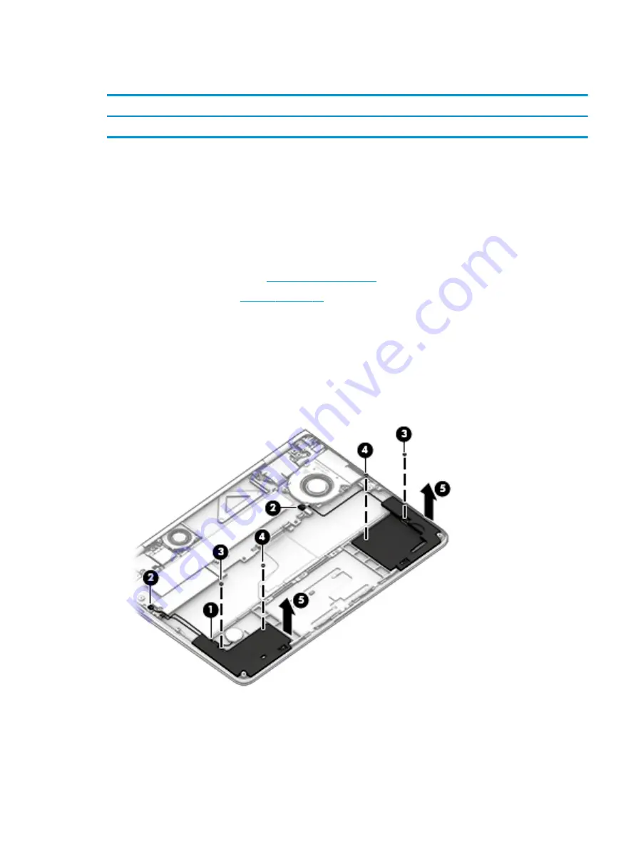
Remove the front speakers:

1.

Remove the RTC battery cable from clip in the right speaker (1).

2.

Disconnect both speaker cables (2) from the system board (to avoid system board damage, see step 5).

3.

Remove the two Phillips PM2.0×3.5 screws (3) and the two Phillips PM1.6×2.0 screws (4) that 
secure the speakers to the computer.

4.

Remove the speakers (5).

Speakers, front

33

Summary of Contents for Spectre x360 Convertible 13-ac000

Page 1: ...HP Spectre x360 Convertible PC Model numbers 13 w000 13 w099 Model numbers 13 ac000 13 ac099 Maintenance and Service Guide IMPORTANT This document is intended for HP authorized service providers only ...

Page 2: ... models Some features may not be available on your computer Not all features are available in all editions of Windows This computer may require upgraded and or separately purchased hardware drivers and or software to take full advantage of Windows functionality Go to http www microsoft com for details Your product does not support Windows 8 or Windows 7 In accordance with Microsoft s support polic...

Page 3: ...hat should only be accessed by an authorized service provider See Chapter 5 Removal and replacement procedures for Customer Self Repair parts for details Accessing parts described in Chapter 6 Removal and replacement procedures for Authorized Service Provider only parts can damage the computer or void your warranty iii ...

Page 4: ...iv Important Notice about Customer Self Repair Parts ...

Page 5: ...llow another hard surface such as an adjoining optional printer or a soft surface such as pillows or rugs or clothing to block airflow Also do not allow the AC adapter to contact the skin or a soft surface such as pillows or rugs or clothing during operation The computer and the AC adapter comply with the user accessible surface temperature limits defined by the International Standard for Safety o...

Page 6: ...vi Safety warning notice ...

Page 7: ...components 15 Miscellaneous parts 18 4 Removal and replacement preliminary requirements 20 Tools required 20 Service considerations 20 Plastic parts 20 Cables and connectors 20 Grounding guidelines 21 Electrostatic discharge damage 21 5 Removal and replacement procedures for Authorized Service Provider parts 24 Bottom cover 24 Battery 26 WLAN module 27 Solid state drive 29 Heat sink fan 30 Audio U...

Page 8: ...update 52 7 Using HP PC Hardware Diagnostics UEFI 53 Downloading HP PC Hardware Diagnostics UEFI to a USB device 53 8 Specifications 55 9 Backing up restoring and recovering 56 Creating recovery media and backups 56 Creating HP Recovery media select products only 56 Using Windows tools 57 Restore and recovery 58 Recovering using HP Recovery Manager 58 10 Power cord set requirements 62 Requirements...

Page 9: ...tel HD Graphics 620 Supports HD Decode DX12 and DP1 2 Panel 13 3 in WLED BrightView UWVA touch screen with flush glass design and multitouch enabled eDP PSR 16 9 ultra wide aspect ratio FHD 1920 1080 uslim flat 2 2 mm panel typical brightness 300 nits UHD 3840 1080 uslim flat 2 0 mm panel typical brightness 340 nits Memory On board system memory Support for LPDDR3 1866 dual channel Support for up ...

Page 10: ...tel Dual band wireless AC 8265 802 11AC 2x2 WiFi BT 4 2 Combo Adaptor non vPro Sensors Accelerometer Gyroscope e Compass Accelerator IC Ports USB Type C ports 2 USB 3 1 Gen 2 with Thunderbolt Gen 3 technology All ports support data transfer power delivery and DisplayPort 1 2 out up to 3840 2160 at 60 Hz USB Type A ports USB 3 1 Gen 1 Supports HP Sleep Charge Combo audio out headphone audio in micr...

Page 11: ...C5 1 meter duckhead power cord with tag label C5 Security Trusted Platform Module 2 0 TPM Operating system Preinstalled Windows 10 Windows 10 Professional For Developed Market ML Windows 10 Home High End ML Windows 10 Home ML For Emerging Market EM SL Windows 10 Home High End EM SL Windows 10 Home EM SL For China SL CPPP Windows 10 Home China Language Edition CPPP Windows 10 Home High End China La...

Page 12: ...ch as a cell phone camera activity tracker or smartwatch and provides high speed data transfer or Connects a display device that has a USB Type C connector providing display output NOTE Your computer may also support a Thunderbolt docking station 3 AC adapter and battery light White The AC adapter is connected and the battery is fully charged Blinking white The AC adapter is disconnected and the b...

Page 13: ...Help and Support and then select HP Documentation NOTE When a device is connected to the jack the computer speakers are disabled 3 Vent Enables airflow to cool internal components NOTE The computer fan starts up automatically to cool internal components and prevent overheating It is normal for the internal fan to cycle on and off during routine operation 4 Power button When the computer is off pre...

Page 14: ...ower Options 5 Power light On The computer is on Blinking The computer is in the Sleep state a power saving state The computer shuts off power to the display and other unneeded components Off The computer is off or in Hibernation Hibernation is a power saving state that uses the least amount of power 6 Chapter 2 External component identification ...

Page 15: ...d of a password logon 6 Infrared camera select products only Allows a facial recognition logon to Windows instead of a password logon The antennas are not visible from the outside of the computer and antenna location varies For optimal transmission keep the areas immediately around the antennas free from obstructions For wireless regulatory notices see the section of the Regulatory Safety and Envi...

Page 16: ...inger gestures to move the pointer or activate items on the screen 2 Left TouchPad button Functions like the left button on an external mouse 3 Right TouchPad button Functions like the right button on an external mouse 8 Chapter 2 External component identification ...

Page 17: ...Lights Component Description 1 Caps lock light On Caps lock is on which switches the key input to all capital letters 2 Mute light Amber Computer sound is off Off Computer sound is on Top 9 ...

Page 18: ...Speakers Component Description Speakers 2 Produce sound 10 Chapter 2 External component identification ...

Page 19: ...Executes specific functions when pressed in combination with the esc key 3 Windows key Opens the Start menu NOTE Pressing the Windows key again will close the Start menu 4 Action keys Execute frequently used system functions NOTE On select products the f5 action key turns the keyboard backlight feature off or on Top 11 ...

Page 20: ... display on both the computer and the monitor Turns the keyboard backlight off or on NOTE To conserve battery power turn off this feature Mutes or restores speaker sound Decreases speaker volume incrementally while you hold down the key Increases speaker volume incrementally while you hold down the key Plays the previous track of an audio CD or the previous section of a DVD or a Blu ray Disc BD St...

Page 21: ...computer sound 2 Vent Enables airflow to cool internal components NOTE The computer fan starts up automatically to cool internal components and prevent overheating It is normal for the internal fan to cycle on and off during routine operation Bottom 13 ...

Page 22: ...er Locate these numbers before you contact support Your service label will resemble one of the examples shown below Refer to the illustration that most closely matches the service label on your computer Component 1 Serial number 2 Product number 3 Warranty period 4 Model number select products only Component 1 HP product name select products only 2 Model name select products only 3 Product number ...

Page 23: ...s and changes product parts For complete and current information on supported parts for the computer go to http partsurfer hp com select the country or region and then follow the on screen instructions Computer major components Computer major components 15 ...

Page 24: ... w099 907338 001 Models 13 ac000 13 ac099 918034 001 4 TouchPad cable 907332 001 5 Speakers front includes left and right speakers and cables 907343 001 6 Speakers rear includes left and right speakers and cables 907344 001 7 Heat sink includes replacement thermal material 907557 001 Fan Kit includes 907333 001 8 Heat sink fan 9 Rear fan 10 System board includes a graphics subsystem with UMA memor...

Page 25: ...id state drive supporting TLC Models 13 w000 13 w099 1 TB 865697 001 512 GB 847110 009 256 GB 847109 011 128 GB 912322 002 Models 13 ac000 13 ac099 1 TB 865697 005 512 GB 847110 014 360 GB 917818 009 256 GB 847109 016 128 GB 912322 001 17 WLAN module Intel Dual band wireless AC 8265 802 11AC 2x2 WiFi BT 4 2 Combo Adaptor non vPro 910264 855 18 Battery 3 cell 58 WHr 5 02 AHr Li ion includes cable 8...

Page 26: ... Type C to HDMI adapter 831752 001 HP USB Type C to RJ 45 adapter 855560 001 Power cord 3 pin C5 black 1 00 m for use in Australia 213356 013 Denmark 213353 013 Europe Austria Belgium Finland France Germany the Netherlands Norway and Sweden 213350 014 India 404827 008 Israel 398063 008 Japan 349756 006 North America 213349 015 People s Republic of China 286497 013 South Africa 361240 007 Switzerla...

Page 27: ...Component Spare part number Models 13 ac000 13 ac099 computer color dark ash silver 919438 001 Screw Kit Models 13 w000 13 w099 907342 001 Models 13 ac000 13 ac099 918035 001 Miscellaneous parts 19 ...

Page 28: ...astic parts Use care when handling the plastic parts Apply pressure only at the points designated in the maintenance instructions Cables and connectors CAUTION When servicing the tablet be sure that cables are placed in their proper locations during the reassembly process Improper cable placement can damage the tablet Cables must be handled with extreme care to avoid damage Apply only the tension ...

Page 29: ...e these precautions Keep components in their electrostatic safe containers until you are ready to install them Before touching an electronic component discharge static electricity by using the guidelines described in this section Avoid touching pins leads and circuitry Handle electronic components as little as possible If you remove a component place it in an electrostatic safe container The follo...

Page 30: ... proper materials are selected to avoid static charging When grounding is not possible use an ionizer to dissipate electric charges Workstation guidelines Follow these grounding workstation guidelines Cover the workstation with approved static shielding material Use a wrist strap connected to a properly grounded work surface and use properly grounded tools and equipment Use conductive field servic...

Page 31: ...m resistance between the operator and ground To be effective the conductive must be worn in contact with the skin The following grounding equipment is recommended to prevent electrostatic damage Antistatic tape Antistatic smocks aprons and sleeve protectors Conductive bins and other assembly or soldering aids Nonconductive foam Conductive tabletop workstations with ground cords of one megohm resis...

Page 32: ... your country or region and then follow the on screen instructions Bottom cover Description Spare part number Bottom cover Models 13 w000 13 w099 907329 001 Bottom cover models 13 ac000 13 ac099 computer color natural silver 918025 001 Bottom cover models 13 ac000 13 ac099 computer color dark ash silver 918026 001 Before disassembling the computer follow these steps 1 Turn off the computer If you ...

Page 33: ...and the six Torx T8M2 0 3 0 screws 3 that secure the bottom cover to the computer 4 Insert a tool into the bottom right corner and pry the cover loose 1 5 Remove the bottom cover 2 Reverse this procedure to install the bottom cover Bottom cover 25 ...

Page 34: ... reduce potential safety issues use only the battery provided with the computer a replacement battery provided by HP or a compatible battery purchased from HP CAUTION Removing a battery that is the sole power source for the computer can cause loss of information To prevent loss of information save your work or shut down the computer through Windows before removing the battery Remove the battery 1 ...

Page 35: ... then shut it down through the operating system 2 Disconnect all external devices connected to the computer 3 Disconnect the power from the computer by first unplugging the power cord from the AC outlet and then unplugging the AC adapter from the computer 4 Remove the bottom cover see Bottom cover on page 24 5 Disconnect the battery cable from the system board see Battery on page 26 Remove the WLA...

Page 36: ...nals on the WLAN module protective sleeves should be installed on the antenna connectors as shown in the following illustration Reverse this procedure to install the WLAN module 28 Chapter 5 Removal and replacement procedures for Authorized Service Provider parts ...

Page 37: ...omputer on and then shut it down through the operating system 2 Disconnect all external devices connected to the computer 3 Disconnect the power from the computer by first unplugging the power cord from the AC outlet and then unplugging the AC adapter from the computer 4 Remove the bottom cover see Bottom cover on page 24 5 Disconnect the battery cable from the system board see Battery on page 26 ...

Page 38: ... Before removing the fan follow these steps 1 Shut down the computer If you are unsure whether the computer is off or in Hibernation turn the computer on and then shut it down through the operating system 2 Disconnect all external devices connected to the computer 3 Disconnect the power from the computer by first unplugging the power cord from the AC outlet and then unplugging the AC adapter from ...

Page 39: ... external devices connected to the computer 3 Disconnect the power from the computer by first unplugging the power cord from the AC outlet and then unplugging the AC adapter from the computer 4 Disconnect the battery cable from the system board see Battery on page 26 Remove the audio USB board 1 Release the zero insertion force ZIF connector 1 to which the cable is attached and then disconnect the...

Page 40: ...er from the computer by first unplugging the power cord from the AC outlet and then unplugging the AC adapter from the computer 4 Remove the bottom cover see Bottom cover on page 24 5 Disconnect the battery cable from the system board see Battery on page 26 Remove the rear left speaker 1 Disconnect the speaker cable 1 from the system board 2 Remove the two Phillips PM2 0 3 5 screws 2 that secure t...

Page 41: ...connect the power from the computer by first unplugging the power cord from the AC outlet and then unplugging the AC adapter from the computer 4 Remove the bottom cover see Bottom cover on page 24 5 Remove the battery see Battery on page 26 Remove the front speakers 1 Remove the RTC battery cable from clip in the right speaker 1 2 Disconnect both speaker cables 2 from the system board to avoid sys...

Page 42: ...on the location as shown by callout 1 in the following image when disconnecting the right front speaker cable 2 Reverse this procedure to install the front speakers 34 Chapter 5 Removal and replacement procedures for Authorized Service Provider parts ...

Page 43: ...tem 2 Disconnect the power from the computer by unplugging the power cord from the computer 3 Disconnect all external devices from the computer 4 Remove the bottom cover see Bottom cover on page 24 5 Remove the battery see Battery on page 26 Remove the TouchPad 1 Release the zero insertion force ZIF connector 1 to which the TouchPad cable is attached and then disconnect the cable from the TouchPad...

Page 44: ...utlet and then unplugging the AC adapter from the computer 4 Remove the bottom cover see Bottom cover on page 24 5 Remove the battery see Battery on page 26 Remove the power button board 1 Release the zero insertion force ZIF connector 1 to which the cable is attached and then disconnect the cable from the power button board 2 Remove the Phillips PM2 0 1 2 screw 2 that secures the board to the com...

Page 45: ... first unplugging the power cord from the AC outlet and then unplugging the AC adapter from the computer 4 Remove the bottom cover see Bottom cover on page 24 5 Remove the battery see Battery on page 26 Remove the RTC battery 1 Disconnect the battery cable from the system board 1 to avoid system board damage see caution and associated image that follows step 2 2 Remove the RTC battery from the com...

Page 46: ...Reverse this procedure to install the RTC battery 38 Chapter 5 Removal and replacement procedures for Authorized Service Provider parts ...

Page 47: ...Intel Core i5 7200U processor 8 GB of system memory 918044 xx1 Intel Core i5 7200U processor 4 GB of system memory 918043 xx1 Before removing the system board follow these steps 1 Shut down the computer If you are unsure whether the computer is off or in Hibernation turn the computer on and then shut it down through the operating system 2 Disconnect all external devices connected to the computer 3...

Page 48: ... 2 Audio cable ZIF connector 40 Chapter 5 Removal and replacement procedures for Authorized Service Provider parts ...

Page 49: ...his step 2 Right front speaker cable to avoid system board damage see caution and associated image that follows this step 3 Right rear speaker cable 4 Rear fan cable 5 Webcam cable 6 Touch pad cable ZIF connector 7 Keyboard cable ZIF connector 8 Backlight cable ZIF connector 9 Power button board cable ZIF connector 10 Left front speaker System board 41 ...

Page 50: ...t front speaker cable 2 and the RTC battery cable 3 4 Remove the two Phillips PM2 0 2 5 screws 1 and the Phillips PM2 0 1 2 broad head screw 2 that secures the system board to the computer 5 Lift the front edge system board 1 until it rests at an angle 42 Chapter 5 Removal and replacement procedures for Authorized Service Provider parts ...

Page 51: ...liding it up and forward at an angle Reverse this procedure to install the system board Note that you can reuse the long strip of Mylar 193 mm 35 mm 0 1 mm that adheres to the system board shown in the following image System board 43 ...

Page 52: ...the AC outlet and then unplugging the AC adapter from the computer 4 Remove the bottom cover see Bottom cover on page 24 and then remove the following components a Battery see Battery on page 26 b Fan see Heat sink fan on page 30 c System board see System board on page 39 Remove the heat sink 1 Position the system board upside down 2 Loosen the three captive Phillips screws 1 that secure the heat ...

Page 53: ...e thoroughly cleaned from the surfaces of the heat sink and the system board each time the heat sink is removed Thermal paste is used on the heat sink 1 and the processor 2 Reverse this procedure to install the heat sink Heat sink 45 ...

Page 54: ...e computer by first unplugging the power cord from the AC outlet and then unplugging the AC adapter from the computer 4 Remove the bottom cover see Bottom cover on page 24 and then remove the following components a Battery see Battery on page 26 b Fan see Heat sink fan on page 30 c System board see System board on page 39 Remove the right rear speaker 1 Remove the two Phillips PM2 0 3 5 screws 1 t...

Page 55: ...llow these steps 1 Shut down the computer If you are unsure whether the computer is off or in Hibernation turn the computer on and then shut it down through the operating system 2 Disconnect all external devices connected to the computer 3 Disconnect the power from the computer by first unplugging the power cord from the AC outlet and then unplugging the AC adapter from the computer 4 Remove the b...

Page 56: ...e unsure whether the computer is off or in Hibernation turn the computer on and then shut it down through the operating system 2 Disconnect the power from the computer by unplugging the power cord from the computer 3 Disconnect all external devices from the computer 4 Remove the bottom cover see Bottom cover on page 24 and then remove the following components 5 Disconnect the battery cable from th...

Page 57: ...assembly to the computer 5 Rotate the display 270 degrees until it is upright as shown in the following image 1 6 Slide the display assembly forward until the display hinges 2 clear the computer Reverse this procedure to install the display assembly Display assembly 49 ...

Page 58: ...n country or region Spare part number For use in Belgium A41 For use in Portugal 131 For use in Bulgaria 261 For use in Romania 271 For use in Canada DB1 For use in Russia 251 For use in the Czech Republic and Slovakia FL1 For use in Saudi Arabia 171 For use in Denmark Finland and Norway DH1 For use in Slovenia BA1 For use in France 051 For use in South Korea AD1 For use in Germany 041 For use in ...

Page 59: ...e on the HP website Most BIOS updates on the HP website are packaged in compressed files called SoftPaqs Some download packages contain a file named Readme txt which contains information regarding installing and troubleshooting the file Determining the BIOS version To decide whether you need to update Setup Utility BIOS first determine the BIOS version on your computer To reveal the BIOS version i...

Page 60: ...y the most recent BIOS update and compare it to the BIOS version currently installed on your computer If the update is more recent than your BIOS version make a note of the date name or other identifier You may need this information to locate the update later after it has been downloaded to your hard drive b Follow the on screen instructions to download your selection to the hard drive Make a note...

Page 61: ...lowing order a Connected USB drive NOTE To download the HP PC Hardware Diagnostics UEFI tool to a USB drive see Downloading HP PC Hardware Diagnostics UEFI to a USB device on page 53 b Hard drive c BIOS 3 When the diagnostic tool opens select the type of diagnostic test you want to run and then follow the on screen instructions NOTE If you need to stop a diagnostic test press esc Downloading HP PC...

Page 62: ...let HP automatically detect your product 4 Select your computer and then select your operating system 5 In the Diagnostic section follow the on screen instructions to select and download the UEFI version you want 54 Chapter 7 Using HP PC Hardware Diagnostics UEFI ...

Page 63: ...ot exceeding 240 V rms NOTE The computer operating voltage and current can be found on the system regulatory label Temperature Operating 5 C to 35 C 41 F to 95 F Nonoperating 20 C to 60 C 4 F to 140 F Relative humidity noncondensing Operating 10 to 90 Nonoperating 5 to 95 Maximum altitude unpressurized Operating 15 m to 3 048 m 50 ft to 10 000 ft Nonoperating 15 m to 12 192 m 50 ft to 40 000 ft NO...

Page 64: ...HP Recovery partition on the computer The backup can be used to reinstall the original operating system in cases where the hard drive is corrupted or has been replaced For information on creating recovery media see Creating HP Recovery media select products only on page 56 For information on the recovery options that are available using the recovery media see Using Windows tools on page 57 Use Win...

Page 65: ...urchased separately to create recovery discs If you use an external optical drive it must be connected directly to a USB port on the computer the drive cannot be connected to a USB port on an external device such as a USB hub If you cannot create DVD media yourself you can obtain recovery discs for your computer from HP See the Worldwide Telephone Numbers booklet included with the computer You can...

Page 66: ... recovery partition to reclaim hard drive space HP Recovery Manager offers the Remove Recovery Partition option For more information see Removing the HP Recovery partition select products only on page 61 Recovering using HP Recovery Manager HP Recovery Manager software allows you to recover the computer to its original factory state by using the HP Recovery media that you either created or that yo...

Page 67: ...overy discs or a recovery USB flash drive This type of recovery can be used only if the hard drive is still working To start HP Recovery Manager from the HP Recovery partition IMPORTANT For a tablet with a detachable keyboard connect the keyboard to the keyboard dock before beginning these steps select products only 1 Type recovery in the taskbar search box select Recovery Manager and then select ...

Page 68: ...rder IMPORTANT For a tablet with a detachable keyboard connect the keyboard to the keyboard dock before beginning these steps 1 Insert the HP Recovery media 2 Access the system Startup menu For computers or tablets with keyboards attached Turn on or restart the computer or tablet quickly press esc and then press f9 for boot options For tablets without keyboards Turn on or restart the tablet and th...

Page 69: ...m the HP Recovery partition So before you remove the Recovery partition create HP Recovery media see Creating HP Recovery media select products only on page 56 NOTE The Remove Recovery Partition option is only available on products that support this function Follow these steps to remove the HP Recovery partition 1 Type recovery in the taskbar search box and then select HP Recovery Manager 2 Select...

Page 70: ...roved by an acceptable accredited agency responsible for evaluation in the country or region where the power cord set will be used The power cord sets must have a minimum current capacity of 10 amps and a nominal voltage rating of 125 or 250 V AC as required by the power system of each country or region The appliance coupler must meet the mechanical configuration of an EN 60 320 IEC 320 Standard S...

Page 71: ...ord and wall plug must bear a T mark and registration number in accordance with the Japanese Dentori Law The flexible cord must be Type VCT or VCTF 3 conductor 1 00 mm conductor size The wall plug must be a two pole grounding type with a Japanese Industrial Standard C8303 7 A 125 V configuration 4 The flexible cord must be Type RVV 3 conductor 0 75 mm conductor size Power cord set fittings applian...

Page 72: ...in general household waste Follow the local laws and regulations in your area for battery disposal HP encourages customers to recycle used electronic hardware HP original print cartridges and rechargeable batteries For more information about recycling programs see the HP Web site at http www hp com recycle 64 Chapter 11 Recycling ...

Page 73: ... assembly removal 48 spare part number 16 48 display panel product description 1 E electrostatic discharge 21 equipment guidelines 23 esc key identifying 11 F fan rear removal 47 spare part number 47 fn key identifying 11 G graphics product description 1 grounding guidelines 21 guidelines equipment 23 grounding 21 packaging 22 transporting 22 workstation 22 H heat sink removal 44 spare part number...

Page 74: ...ive 1 video 1 wireless 2 product name 1 product name and number computer 14 R rear fan removal 47 spare part number 47 recover options 58 recovery discs 57 59 HP Recovery Manager 58 media 59 starting 59 supported discs 57 system 58 USB flash drive 59 using HP Recovery media 57 recovery media creating 56 creating using HP Recovery Manager 57 recovery partition removing 61 regulatory information reg...

Page 75: ...wer connector and Thunderbolt port identifying 4 USB Type C to USB Type A dongle spare part number 18 USB to Gigabit RJ 45 adapter spare part number 18 V vents identifying 5 13 video product description 1 W Windows system restore point 56 57 Windows key identifying 11 Windows tools using 57 wireless certification label 14 wireless product description 2 WLAN antennas identifying 7 WLAN device 14 WL...

Reviews: