background image

56

Install and secure a drive

Install and secure a drive

Before you begin

You have completed these tasks:
• Obtained an unsecured replacement drive of the same type, speed, and capacity of the drive you are

removing. You cannot replace a secured drive with a drive that does not support encryption or a drive

that is currently secured by a different controller. If the drive is currently secured, you must erase the

drive to delete its security attributes. See 

Erase a drive that supports encryption

 on page 40.

• Read the guidelines for maintaining disk drives. See 

Drive maintenance guidelines

 on page 52.

• Read the guidelines for protecting hardware from electrostatic discharge. See 

About electrostatic

discharge

 on page 17.

• Removed the failed drive. See 

Remove a secured drive

 on page 54.

Procedure
1.

Carefully remove the replacement drive from its packaging.

2.

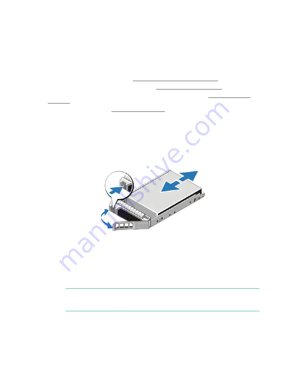
Hold the drive by the edge of the plastic drive carrier and press the release button to release the drive

handle.

3.

Rotate the handle outwards.

4.

Orient the drive properly.

5.

Grasp the edge of the plastic drive carrier and slowly insert the drive into the slot, stopping when you

feel resistance.

6.

Simultaneously rotate the handle upward and press the drive completely into the slot.

NOTE: 

The RAID set begins rebuilding to configure the new drive and to ecrypt it with the existing

Security Key.

7.

Examine the LEDs on the drive and event messages to ensure the drive is operational.

Summary of Contents for SimpliVity OmniCube CN-1400

Page 1: ...Hewlett Packard Enterprise SimpliVity OmniCube CN 1400 CN 2400 CN 3400 and CN 5400 Series Hardware Installation and Maintenance Guide Part number 760 000249 Rev A Published June 2017 ...

Page 2: ...10215 2 IN 368 CHENP 2014 JP 6059216 US 9 436 748 US 2016 0371354 AU 2013222325 BR 112014020806 9 CA 2 865 240 CN 201380017261 8 EP 13710149 9 HK 15100889 7 IN 6929 CHENP 2014 JP 5902323 US 9 032 183 US 2015 0242315 AU 2014308938 BR 112016003205 5 CA 2 921 039 CN 201480045910 X EP 14759406 3 IN 201647008897 JP 2016 536408 US 9 043 576 US 2015 0254256 AU 2016206826 BR 112016028144 6 CA WO2016 11521...

Page 3: ...ck the shipping carton 17 Shipping carton contents 18 Hardware not supplied in the shipping carton 19 Install the server enclosure in a rack 20 Mount the enclosure in the rails 21 Connect the network cables 22 Connect the power cables 23 Organize the cables 24 Power on the system 25 Attach the OmniCube bezel 25 Detach the OmniCube bezel 27 Chapter 3 Configure the IPMI port for remote management 28...

Page 4: ... About network interface monitoring 50 Chapter 6 Drive maintenance 52 Drive maintenance guidelines 52 Remove a drive 53 Remove a secured drive 54 Install a drive 55 Install and secure a drive 56 Chapter 7 Power supply maintenance 57 Power supply maintenance guidelines 57 Remove a power supply 57 Install a power supply 58 Chapter 8 Network cabling options 60 About the 10GbE only network configurati...

Page 5: ...servers for easy on demand scalability with no disruption to users Hardware components Each OmniCube model provides different hardware configurations for storage compute and memory Table 1 Hardware components by hybrid model hybrid models may contain both HDD and SSD physical drives Component CN 1400 CN 2400 and CN 2400 E CN 3400 CN 5400 and CN 5400 E Model Intel Xeon E5 2600 V3 or V4 series CN 24...

Page 6: ...3 1 2TB V4 CN 2400 E 1 2TB V4 1TB 1 2TB Interface SAS SAS SAS SAS Dimension 2 5 2 5 carrier 2 5 2 5 carrier 2 5 2 5 carrier 2 5 2 5 carrier RAID Type RAID5 RAID6 RAID60 RAID60 RPM 7 200 CN 2400 7 200 V3 10 000 V4 CN 2400 E 10 000 V4 7 200 10 000 Front HDD Drives Self Encrypting Drives No CN 2400 E only No CN 5400 E only Quantity 2 2 2 2 Capacity 300GB 300GB 300GB 300GB Interface SAS SAS SAS SAS Di...

Page 7: ...memory sizes greater than 384GB Memory Size and Frequency Dual CPU N A 256GB 8x32GB RDIMM 2133MHz or 2400MHz 384GB 8x16GB 8x32GB RDIMM 2133MHz or 2400MHz 512GB 16x32GB RDIMM 2133MHz or 2400MHz 768GB 24x32GB RDIMM 1866MHz or 2133MHz Contact your SimpliVity sales representative to learn about memory sizes greater than 768GB Power Supply Units Hot swappable integrated fans 2 x 750W 2 x 1100W Embedded...

Page 8: ...hysical drives only Component CN 2400 F CN 3400 F CN 5400 F Model Intel Xeon E5 2600 V4 series CPU Count 1 or 2 CPU Core Count 8 or greater Speed in GHz 2 3GHz or greater CPU Wattage 145W or less Quantity CN 2400 F 5 CN 3400 F 10 CN 5400 F 14 Capacity 1 6TB Interface SATA Dimension 2 5 2 5 carrier RAID Type CN 2400 F RAID5 CN 3400 F RAID6 CN 5400 F RAID6 Front SSD Drives Self Encrypting Drives No ...

Page 9: ...6GB 8x32GB RDIMM 2133MHz or 2400MHz 384GB 8x16GB 8x32GB RDIMM 2133MHz or 2400MHz 512GB 16x32GB RDIMM 2133MHz or 2400MHz 768GB 24x32GB RDIMM 1866MHz or 2133MHz Contact your SimpliVity sales representative to learn about memory sizes greater than 768GB Power Supply Units Hot swappable integrated fans 2 x 1100W Embedded 2 x 10GbE SFP and 2 x 1GbE Network Interfaces VM Network optional Not applicable ...

Page 10: ...Shows hardware error conditions 3 System identification button System identification button and system identification connector The system identification button helps you locate a system within a rack If you push the system identification button on the back panel or the front panel the system identification buttons on the front panel and the back panel flash blue Push a system identification butto...

Page 11: ... are empty CN 3400 F Contains 10 drives Drives 0 to 9 are SSDs Drives 10 to 23 are empty CN 5400 F Contains 14 drives Drives 0 to 13 are SSDs Drives 14 to 23 are empty If you pull the enclosure from the rack the disk numbering scheme appears on a label attached to the top of the enclosure 6 Video input Enables you to connect a monitor as part of a keyboard video and mouse KVM setup for local admin...

Page 12: ...x1GbE network cards in these slots as shown in slot 2 used by guest VMs only A system with a single CPU does not contain riser 1 A plate is installed in place of riser 1 2 Accelerator Installed in PCIe slot 5 of riser 2 but also occupies slot 4 The card has two LEDs that continuously glow green to indicate normal operation 3 RAID controller RAID Controller for the rear boot drives installed in PCI...

Page 13: ...nector Video connector that enables you to connect a monitor or keyboard video monitor KVM device 8 USB connectors Two USB 3 0 compliant ports for connecting USB devices to the system 9 10GbE ports Two 10GbE network interfaces numbered 1 and 2 Each 10GbE interface has link top and activity bottom round LEDs These interfaces are dedicated to SimpliVity Storage and Federation networks 10 1GbE ports ...

Page 14: ...Maximum depth from rack flange 75 58 29 75 The maximum weight of a system with all storage drives installed is 30 4 kg or 67 02 lbs Power and thermal OmniCube servers have two redundant power supplies with specific power and thermal specifications Table 5 OmniCube Power and Thermal Specifications Specification Description Current consumption 10A 5A Supply voltage 100 240V AC autoranging Make sure ...

Page 15: ...hock operating Six consecutively executed shock pulses in the positive and negative x y and z axes of 40 G for up to 2 3 ms Shock storage Six consecutively executed shock pulses in the positive and negative x y and z axes one pulse on each side of the system of 71 G for up to 2 ms Altitude and airborne contaminants OmniCube servers have limits for altitude and airborne contaminants under operating...

Page 16: ...3 1 2011 GB9254 2008 CLASS A ZEK 01 4 08 About hardware upgrades If you need to upgrade the server hardware components contact Customer Support WARNING Never install additional options other than those approved for installation by Customer Support Doing so will void your warranty and might cause serious server instability and potential data loss About firmware revisions The OmniStack software requ...

Page 17: ...rge When not installed in a rack store server hardware in its original packaging or place on a sturdy surface that is protected from electrostatic discharge When handling server hardware components always use the electrostatic wrist strap provided or a similar form of ESD protection Unpack the shipping carton You unpack the shipping carton to prepare the system hardware components for installation...

Page 18: ...on cable and the installation instructions Do not open this box until the end of the installation procedure when you are ready to organize the system cables 6 Remove the accessory pack callout 3 which contains SimpliVity bezel Power and network cables Software and documentation flash drive Quick Start posters and international Product Information Guide 7 If you are not ready to install the system ...

Page 19: ...nse Agreement Hardware not supplied in the shipping carton Your network environment might require additional hardware components not supplied in the shipping carton Hardware Description Application Rack 19 inch 48 3 cm four post toolless rack Provides easy access to the server hardware in your computing environment 1 GbE data cables Two Category 5E or Category 6 cables with RJ45 connectors An opti...

Page 20: ...ck with two power distribution units PDU feeding separate outlet strips with sufficient vacant outlets on each strip Ensure the rack is installed and stabilized or bayed according to the manufacturer s instructions WARNING When servicing an enclosure in a rack extend only one enclosure at a time to prevent the rack from tipping Rack installation guidelines There are guidelines to help you successf...

Page 21: ...Align the top of the rail brackets with the U space markers on the front and rear rack columns callouts 1 and 2 Figure 5 Rail kit installation 3 Firmly push the brackets onto the rack columns so that the blue latches callout 4 engage and lock 4 Make sure that both the front and rear bracket latches are closed and the rails are secure 5 Repeat Step 1 through Step 4 for the left rail NOTE The blue b...

Page 22: ... down callout C engaging the lugs in the J slots 5 Ensure all eight lugs on the enclosure are seated firmly in the J slots in the rails and that the lug lock callout D engages 6 Press the rail lock button callout A and slide the enclosure into the rack callout E 7 Ensure the enclosure retention lock callout F closes completely Next steps You can now connect the power cables to the OmniCube servers...

Page 23: ...hese interfaces after deployment NOTE If the optional interfaces are connected when you deploy the system the ports for the Federation network might not be configured correctly For help with resolving this error contact Customer Support Next steps You can now optionally use the Cable Management Arm CMA to organize the cables Connect the power cables An OmniCube server includes two hot swappable 75...

Page 24: ...nect the network cables Organize the cables Procedure overview If you do not want to use the cable management arm CMA use the two hook and loop straps provided in the rail kit to organize the power and network cables NOTE Make sure you have sufficient slack in the cables to fully extend the enclosure from the rack until the rails are safely locked in the extended position Procedure 1 Insert the ou...

Page 25: ...o power on the system 3 Check that the health indicator on the front panel changes from flashing amber to steady blue within approximately 4 minutes 4 Check that the two LEDs on the Accelerator card at the rear of the system are steady green Attach the OmniCube bezel You attach the OmniCube bezel to the front panel of the system to physically secure the front drives ensure proper airflow and to pr...

Page 26: ... 10 OmniCube Bezel Lugs 2 Insert the bezel tabs into the front panel mounting lugs Figure 11 OmniCube Bezel Tabs 3 Rotate the left side of the bezel inward toward the front panel and push firmly until you hear the latch click and engage ...

Page 27: ... system to gain access to the front drives Procedure 1 Hold the blue cube handle to detach the bezel and push up on the release latch Figure 12 OmniCube Bezel Latch 2 Rotate the left side of the bezel outward from the front panel and pull to the left to simultaneously disengage the tabs on the right side of the bezel ...

Page 28: ...et cable from the Ethernet port on the laptop to the IPMI Ethernet port on the rear of the OmniCube server 2 If necessary change the IPv4 address of the Ethernet port on your laptop a Open Network and Sharing Center and select the Ethernet port connection This is typically Local Area Connection b Click Properties Internet Protocol Version 4 TCP IPv4 c Record the current settings so that you can re...

Page 29: ...ment Interface IPMI web GUI to launch the Virtual Console which you use to access advanced system options Before you begin You have configured the IPMI port See Configure the IPMI port for remote management on page 28 NOTE You can use the Virtual Console to power cycle the OmniCube host and access System Setup From System BIOS System Security you can enter a new setup password to prevent unwanted ...

Page 30: ...use the DNS RAC to reference the OmniCube host This prevents problems if the DHCP lease is renewed and a different IP address is assigned to the IPMI port You have ensured that the ports required for network communication are open You have the following information and items An IP address The address can be static or assigned by DHCP A static address for the gateway subnet mask and optionally up t...

Page 31: ...e a unique passphrase for each RAID controller on which you create a Security Key The front drives which are controlled by the H730P Mini Adapter RAID controller store user data and data for the OmniStack software You cannot encrypt the rear boot drives which are controlled by the PERC H330 Mini RAID controller Since the rear boot drives do not contain user data you do not need to encrypt them You...

Page 32: ...s data and security attributes such as a lost or forgotten passphrase You cannot erase a drive that contains secured virtual drives Access the PERC BIOS Configuration Utility Before you begin You have completed these tasks Backed up all virtual machines on the OmniCube host The system is in a safe state so that you can restart it and load the BIOS to access the BIOS Configuration Utility Configure...

Page 33: ...D 5 for the CN 5400 E and review the Secured field to the right Yes indicates that the virtual disk is secure b Select Disk Group 0 RAID 6 for the CN 2400 E or Disk Group 0 RAID 60 for the CN 5400 E and review the Secured field to the right c If the secured field is No it means the disk group is not secured Follow the steps in Secure disk groups with a Security Key on page 35 to secure the disk 3 ...

Page 34: ... Disks and review the Security Status column 2 Select Storage Virtual Disks and review the Secured column Create a Security Key Before you begin You have displayed the PERC BIOS Configuration Utlity on the computer connected to the OmniCube host See Access the PERC BIOS Configuration Utility on page 32 Procedure 1 Select the PERC H730P Mini controller on the Virtual Disk Management screen 2 Press ...

Page 35: ...he RAID controller See Secure disk groups with a Security Key on page 35 Secure disk groups with a Security Key Before you begin You have completed these tasks Created a Security Key for the RAID controller that is connected to the disk groups See Create a Security Key on page 34 Displayed the PERC BIOS Configuration Utility on the computer connected to the OmniCube host See Access the PERC BIOS C...

Page 36: ...controller 2 Press F2 3 Select Secure Disk Group and then select Yes to confirm 4 Select the RAID 6 CN 2400 E or RAID 60 CN 5400 E disk group 5 Press F2 6 Select Secure Disk Group and then select Yes to confirm Results Both disk groups and all virtual disks inside them are now secured with the Security Key Delete disk groups Before you begin ...

Page 37: ... RAID5 CN 5400 E disk group is on the SSD drives which are reserved for SimpliVity and the RAID6 CN 2400 E or RAID60 CN 5400 E disk group is on the HDD drives which store user data You delete a disk group to delete all of its virtual disks You can also delete individual viritual disks from a disk group Caution When you delete a disk group all data on the underlying physical disks is lost Procedure...

Page 38: ...e completed these tasks Created a Security Key for the RAID controller on which you want to change the passphrase See Create a Security Key on page 34 Obtained the passphrase for the current Security Key Displayed the PERC BIOS Configuration Utlity on the computer connected to the OmniCube host See Access the PERC BIOS Configuration Utility on page 32 Procedure 1 Select the PERC H730P Mini control...

Page 39: ...elect OK 8 Select Yes to confirm Delete a Security Key Before you begin You have completed these tasks Migrated all virtual machines VM off of the OmniCube host Displayed the PERC BIOS Configuration Utlity on the computer connected to the OmniCube host See Access the PERC BIOS Configuration Utility on page 32 Procedure 1 Use the arrow keys to select the PERC H730P Mini controller 2 Select the PERC...

Page 40: ...onfirm 6 Select the other disk group and repeat Step 4 on page 40 and Step 5 on page 40 to delete it 7 Select the PERC H730P Mini controller 8 Press F2 and select Delete Key 9 Select Yes to confirm deleting the key The key is deleted and the disks are now erased Erase a drive that supports encryption Before you begin You have completed these tasks ...

Page 41: ...anently remove all security attributes from the drive including a lost or forgotten passphrase For example if you replace a drive and the replacement drive is secured with a passphrase for a Security Key on a different controller the new RAID controller cannot access or secure the drive You must erase the replacement drive to remove the security attributes and then secure it using the key from the...

Page 42: ...42 Erase a drive that supports encryption 5 Press Enter and select Yes to confirm The drive is erased and its security attributes are deleted ...

Page 43: ...nt panel displays diagnostic indicators that glow when the system is functioning properly and when a hardware related error occurs The indicators can help you correct problems before they affect service levels Figure 13 Diagnostic indicator LEDs Table 6 Diagnostic indicator descriptions Callout Description 1 Health indicator If no errors exist the indicator is steady blue The health indicator flas...

Page 44: ...re user and Federation data and are protected by RAID which provides different protection for each model A CN 2200 CN 2400 or CN 2400 E model can tolerate up to two hard disk drive HDD failures and one solid state drive SSD failure simultaneously without data loss A CN 2400 F containing all flash drives can tolerate a single solid state drive SSD failure without data loss A CN 3400 F containing al...

Page 45: ...tatus LED LED Pattern Drive Status Description Flashes green two times per second Identifying the drive or preparing the drive for removal Off Drive ready for removal or all drives are initializing The drive status LED remains off while the drives are initializing after the system is turned on Do not remove a drive during this time Flashes green amber and off Predicted drive failure Flashes amber ...

Page 46: ...t No disk activity Flashing or steady green Read Write I O activity is occurring About front drive numbering The front drives are numbered for identification purposes Figure 15 CN 1400 drive numbering The drives are numbered 0 to 23 Drives 0 to 1 are SSDs and drives 2 to 5 are HDDs Figure 16 CN 2400 drive numbering The drives are numbered 0 to 23 Drives 0 and 1 are SSDs and drives 2 to 9 are HDDs ...

Page 47: ...ure 18 CN 2400 F drive numbering The drives are numbered 0 to 23 Drives 0 to 4 are SSDs and drives 5 to 23 are empty Figure 19 CN 3400 F drive numbering The drives are numbered 0 to 23 Drives 0 to 9 are SSDs and drives 10 to 23 are empty Figure 20 CN 5400 F drive numbering The drives are numbered 0 to 23 Drives 0 to 13 are SSDs and drives 14 to 23 are empty ...

Page 48: ...rred Table 9 Power supply LED States LED State Off Indicates no power present Steady green Indicates the power supply is connected to a power source is operational and is supplying power to the system Flashing yellow Indicates a problem with the power supply Flashing green When performing a hot swap of a power supply with the system powered on this LED indicates that the newly installed power supp...

Page 49: ...2 off Firmware is not responding to health check Flashing yellow Steady green Power on self test POST is executing Steady yellow Steady red POST failed POST Steady green Steady green Normal operation passed POST State save Steady yellow Flashing green NVRAM state save is in progress State restore Flashing yellow Flashing green NVRAM state restore is in progress Upgrade Flashing green Flashing gree...

Page 50: ...tarting the server prompts the Accelerator card to fail and use its backup firmware If both LEDs on the Accelerator card are not glowing steady green or the server fails to return to normal operation contact Customer Support Procedure 1 In your hypervisor management interface locate the OmniCube host or OmniStack host with the problem Accelerator card 2 Shut down and power off the server as explai...

Page 51: ...ED Activity Status bottom LED Description Off Off No network connection Off Flash green Sending or receiving network data Steady green Off Connected to the network Table 13 1GB interface LED states Link Status left LED Activity Status right LED Status Description Off Off No network connection Green Off Connected to the network at maximum port speed Amber Off Connected to the network at less than m...

Page 52: ...k drives or place anything on top of a drive Protect drives from electrostatic discharge Wear an electrostatic wrist strap when handling a drive unless it is protected from electrostatic discharge Handle drives carefully Hold a drive only by the plastic part of the carrier or the handle Do not drop or jolt a drive or force a drive into a drive slot Do not leave a drive slot empty Each drive slot m...

Page 53: ... a failed drive unless you have a replacement drive or blank carrier ready to install If the system is in a Federation using incompatible drives might cause your Federation to function incorrectly Also performance might be degraded while a drive is defective or missing Procedure 1 Remove the bezel if necessary 2 Examine the drive LEDs to identify the failed drive 3 Press the release button to rele...

Page 54: ...for protecting hardware from electrostatic discharge See About electrostatic discharge on page 17 Procedure overview NOTE If the system is in a Federation using incompatible drives might cause your Federation to function incorrectly Also performance might be degraded while a drive is defective or missing Procedure 1 Remove the bezel if necessary 2 Examine the drive LEDs to identify the failed driv...

Page 55: ...ic discharge Removed the failed drive Procedure overview NOTE Do not leave a drive slot empty Do not remove a failed drive unless you have a replacement drive or blank carrier ready to install Procedure 1 Carefully remove the replacement drive from its packaging 2 Hold the drive by the edge of the plastic drive carrier and press the release button to release the drive handle Figure 25 Drive instal...

Page 56: ...nes for protecting hardware from electrostatic discharge See About electrostatic discharge on page 17 Removed the failed drive See Remove a secured drive on page 54 Procedure 1 Carefully remove the replacement drive from its packaging 2 Hold the drive by the edge of the plastic drive carrier and press the release button to release the drive handle 3 Rotate the handle outwards 4 Orient the drive pr...

Page 57: ...d or failing power supply as soon as possible Replace a power supply only with a power supply of the same type and wattage Contact Customer Support for replacement power supplies Remove a power supply You replace a failed or failing power supply as soon as possible Before you begin You have completed these tasks Obtained a replacement power supply of the same type and wattage Read the guidelines f...

Page 58: ...ement power supply of the same type and wattage Read the guidelines for maintaining power supplies Read the guidelines for protecting hardware from electrostatic discharge Procedure 1 Carefully remove the replacement power supply from its packaging 2 Orient the power supply so that the release latch is in the appropriate location depending on the model 3 Slide the power supply into the empty slot ...

Page 59: ...n by the orange spring loaded clip 5 Connect and secure the power cable to the new power supply 6 Ensure that the power cables are fully inserted at both ends 7 Ensure that the new power supply is operational 8 Examine the LEDs and event messages to ensure the power supply is operational ...

Page 60: ... Federation and Management You select the configuration that best meets the needs of your environment About the 10GbE only network configuration The minimum network configuration for a Federation with two OmniCube servers uses redundant 10GbE connections to two 10GbE switches This configuration uses VLANs to separate the SimpliVity Storage Federation and Management networks Figure 26 10GbE only ne...

Page 61: ...rk Figure 27 Direct connected Storage network configuration Configuration guidelines You cannot use direct connections for the Storage and Federation networks if you have three or more systems in a Federation datacenter or cluster For each system you can use two SFP Direct Attach Twinax cables or Fiber Optic cables to directly connect the 10GbE network interfaces For each system you use two networ...

Page 62: ...bE connections to 1GbE switches shown below or optionally 10GbE connections to 10GbE switches for the Management network Figure 28 Switch connected Storage network configuration Configuration guidelines For each system use two SFP Direct Attach active cables or Fiber Optic cables to connect the 10GbE network interfaces to different 10GbE switches For each system use two network cables to connect t...

Page 63: ...ce element such as a button or tab with which a user interacts Command Line formatting SimpliVity documentation uses the following format for CLI commands command option variable where command is the name of the command and should be typed exactly as shown option is a command option and should be typed exactly as shown variable is an option variable and should be replaced with the required value I...

Page 64: ...tainer for virtual machine files including compute and storage resources For more information refer to your hypervisor documentation failure domain A collection of OmniStack hosts that serve as potential high availability failover targets for each other for purposes of high availability and disaster recovery Federation A collection of SimpliVity OmniStack hosts and clusters managed in a single glo...

Page 65: ...pe com info EIL Single Point of Connectivity Knowledge SPOCK Storage compatibility matrix http www hpe com storage spock Storage white papers and analyst reports http www hpe com storage whitepapers Customer Self Repair http www hpe com support selfrepair Insight Remote Support http www hpe com info insightremotesupport docs Regulatory information To view the regulatory information for your produc...

Page 66: ...o environment Documentation feedback Hewlett Packard Enterprise is committed to providing documentation that meets your needs To help us improve the documentation send any errors suggestions or comments to Documentation Feedback mailto docsfeedback hpe com When submitting your feedback include the document title part number edition and publication date located on the front cover of the document Fo...

Reviews: