


Front Bezel
1.
Prepare the computer for disassembly (
Preparation for Disassembly on page 35
).
2.
Remove the access panel (
Computer Access Panel on page 43
).
3.
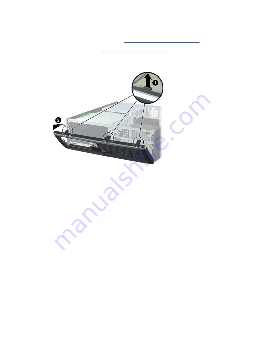
Lift up the three tabs on the side of the bezel
(1)
, then rotate the bezel off the chassis
(2)
.
Figure 6-11
Removing the Front Bezel
To install the front bezel, reverse the removal procedure.
44
Chapter 6 Removal and Replacement Procedures Small Form Factor (SFF) Chassis
Summary of Contents for SignagePlayer mp8000r
Page 1: ...Maintenance and Service Guide HP SignagePlayer mp8000r and mp8000s ...
Page 4: ...iv About This Book ...
Page 10: ...x ...
Page 13: ...Quick Release 3 ...
Page 14: ...4 Chapter 1 Displays and Quick Release Installation ...


