background image


Component identification  45 

Component identification 

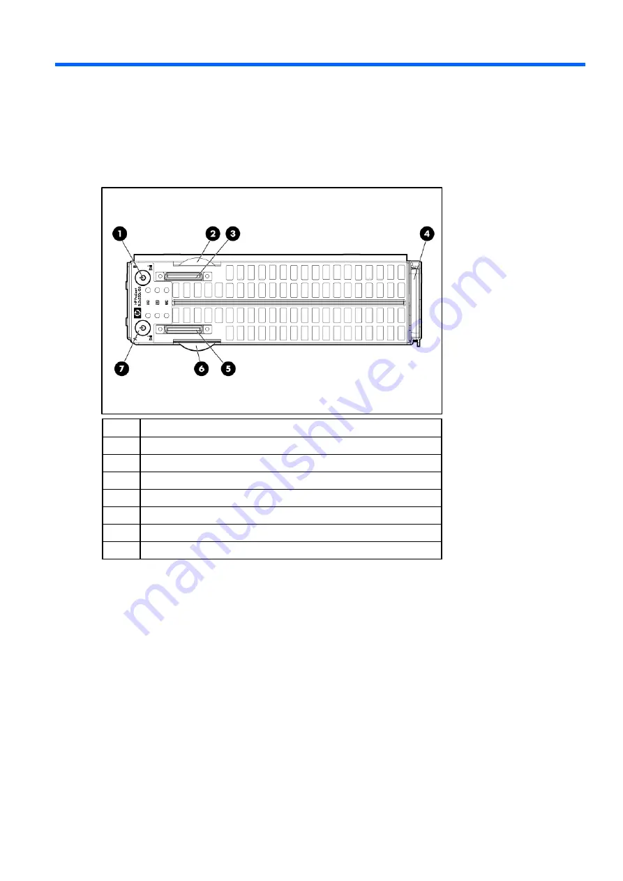
Front panel components 


Item Description 

Workstation B Power On/Standby button 

Workstation B serial label pull tab 

Workstation B HP c-Class Blade SUV Cable connector* 

Workstation blade handle 

Workstation A HP c-Class Blade SUV Cable connector* 

Workstation A serial label pull tab 

Workstation A Power On/Standby button 


* The SUV connector and the HP c-Class Blade SUV Cable are for some workstation blade configuration and 
diagnostic procedures. 


Summary of Contents for ProLiant xw2x220c - Blade Workstation

Page 1: ...HP ProLiant xw2x220c Blade Workstation Maintenance and Service Guide Part Number 518100 001 December 2008 First Edition ...

Page 2: ...technical or editorial errors or omissions contained herein Microsoft and Windows are U S registered trademarks of Microsoft Corporation Intel and Xeon are trademarks or registered trademarks of Intel Corporation or its subsidiaries in the United States and other countries Intended audience This guide is for an experienced service technician HP assumes you are qualified in the servicing of compute...

Page 3: ...r 17 Cache module battery 22 Battery cable 23 Mezzanine card 24 Workstation A system board 25 Workstation B system board 31 System battery 38 Cabling 40 BBWC battery cabling 40 Using the HP c Class Blade SUV Cable 40 Connecting locally to a workstation blade with video and USB devices 40 Diagnostic tools 43 Troubleshooting resources 43 HP Insight Diagnostics 43 Integrated Management Log 43 USB sup...

Page 4: ...kstation B DIMM slots 50 Mezzanine connector definitions 50 System maintenance switch 51 HP c Class Blade SUV Cable 51 Specifications 52 Environmental specifications 52 Workstation blade specifications 52 Acronyms and abbreviations 53 Index 55 ...

Page 5: ... be shipped for next business day delivery Same day or four hour delivery may be offered at an additional charge where geography permits If assistance is required you can call the HP Technical Support Center and a technician will help you over the telephone HP specifies in the materials shipped with a replacement CSR part whether a defective part must be returned to HP In cases where it is require...

Page 6: ...Processor a 3 00 GHz Intel Xeon model E5450 quad core processor 457878 001 Optional2 b 2 83 GHz Intel Xeon model E5440 quad core processor 460490 001 Optional2 c 2 66 GHz Intel Xeon model E5430 quad core processor 457877 001 Optional2 d 2 50 GHz Intel Xeon model E5420 quad core processor 460491 001 Optional2 e 2 33 GHz Intel Xeon model E5410 quad core processor 460492 001 Optional2 ...

Page 7: ...A 461666 001 Optional2 b Workstation B 461665 001 Optional2 5 SATA hard drives a 250 GB 2 5 in 5400 rpm 460427 001 Mandatory1 b 200 GB 2 5 in 5400 rpm 459617 001 Mandatory1 c 120 GB 2 5 in 5400 rpm 459616 001 Mandatory1 6 System battery lithium 3V 234556 001 Mandatory1 7 Cache module battery cable 409125 001 Mandatory1 8 Cache module battery 398648 001 Mandatory1 9 HP c Class Blade SUV Cable 41600...

Page 8: ...speeds or cache sizes 1 Mandatory Parts for which customer self repair is mandatory If you request HP to replace these parts you will be charged for the travel and labor costs of this service 2 Optional Parts for which customer self repair is optional These parts are also designed for customer self repair If however you require that HP replace them for you there may or may not be additional charge...

Page 9: ...cts in static safe containers Keep electrostatic sensitive parts in their containers until they arrive at static free workstations Place parts on a grounded surface before removing them from their containers Avoid touching pins leads or circuitry Always be properly grounded when touching a static sensitive component or assembly Workstation blade warnings and cautions WARNING To reduce the risk of ...

Page 10: ...losure This symbol on an RJ 45 receptacle indicates a network interface connection WARNING To reduce the risk of electric shock fire or damage to the equipment do not plug telephone or telecommunications connectors into this receptacle This symbol indicates the presence of a hot surface or hot component If this surface is contacted the potential for injury exists WARNING To reduce the risk of inju...

Page 11: ...the workstation A and workstation B Power On Standby buttons for more than 4 seconds to force the workstation blade to shut down This method forces the workstation blade to enter standby mode without properly exiting applications and the OS It provides an emergency shutdown method in the event of a hung application CAUTION To prevent damage to the workstation or the operating system always power d...

Page 12: ...ury from hot surfaces allow the drives and the internal system components to cool before touching them CAUTION To prevent damage to electrical components properly ground the workstation blade before beginning any installation procedure Improper grounding can cause ESD Remove workstation B assembly For access component identification see Access components on page 47 To remove the component 1 Power ...

Page 13: ...tion B serial label pull tab 2 Engage the front edge of workstation B assembly with the front edge of workstation A assembly CAUTION Route the cache module battery cables so that they do not become pinched when the workstation B assembly is installed 3 Lower workstation B assembly onto workstation A assembly 4 Align the signal and power connectors on workstation B assembly with the corresponding c...

Page 14: ...e component 1 Power down the workstation blade on page 11 2 Remove the workstation blade on page 11 3 Access the internal workstation components on page 12 4 Remove the hard drive assembly 5 Remove the hard drive from the carrier CAUTION To avoid damage to the hard drive use the retaining screw to lower the hard drive assembly into position To replace the component reverse the removal procedure ...

Page 15: ... the DIMM IMPORTANT Always install memory in pairs of two identical DIMMs To replace the component reverse the removal procedure Heatsink WARNING To reduce the risk of personal injury from hot surfaces allow the drives and the internal system components to cool before touching them To remove the component 1 Power down the workstation blade on page 11 2 Remove the workstation blade on page 11 3 Acc...

Page 16: ...swab Allow the alcohol to evaporate before continuing 2 Remove the thermal interface protective cover from the spare heatsink CAUTION Heatsink retaining screws should be tightened in diagonally opposite pairs in an X pattern IMPORTANT When installing the heatsink align the guide pins on the processor retention bracket with the alignment holes in the heatsink ...

Page 17: ...ket CAUTION To avoid damage to the processor Handle the processor only by the edges Do not touch the bottom of the processor especially the contact area CAUTION To prevent possible workstation malfunction and damage to the equipment multiprocessor configurations must contain processors with the same part number CAUTION To prevent possible workstation blade overheating always populate processor soc...

Page 18: ... processor protective cover Always install the processor protective cover if the processor is removed from the socket To remove the component 1 Power down the workstation blade on page 11 2 Remove the workstation blade on page 11 3 Access the internal workstation components on page 12 4 Remove the heatsink 5 Open the processor retaining latch and the processor socket retaining bracket ...

Page 19: ...r has separated from the installation tool carefully re insert the processor in the tool 2 Align the processor installation tool with the socket and install the spare processor CAUTION The processor is designed to fit one way into the socket Use the alignment guides on the processor and socket to properly align the processor with the socket Refer to the workstation blade hood label for specific in...

Page 20: ...Removal and replacement procedures 20 3 Press down firmly until the processor installation tool clicks and separates from the processor and then remove the processor installation tool ...

Page 21: ...low the alcohol to evaporate before continuing 6 Apply all the grease to the top of the processor in one of the following patterns to ensure even distribution CAUTION Heatsink retaining screws should be tightened in diagonally opposite pairs in an X pattern IMPORTANT When installing the heatsink align the guide pins on the processor retention bracket with the alignment holes in the heatsink ...

Page 22: ... page 13 9 Install the workstation blade Cache module battery To remove the component 1 Power down the workstation blade on page 11 2 Remove the workstation blade on page 11 3 Access the internal workstation components on page 12 4 Remove the workstation A USB key if installed 5 Disconnect the battery cables from the battery packs ...

Page 23: ...e cache batteries from the battery tray To replace the component reverse the removal procedure Battery cable To remove the component 1 Power down the workstation blade on page 11 2 Remove the workstation blade on page 11 3 Access the internal workstation components on page 12 ...

Page 24: ...ps 7 Remove the cable shield from the upper mezzanine card thumbscrew and the signal connector 8 Disconnect the cable from the upper cache module 9 Remove the upper mezzanine card Mezzanine card on page 24 10 Disconnect the remaining cable from the lower cache module 11 Remove the lower mezzanine card Mezzanine card on page 24 12 Remove the failed cable CAUTION To prevent battery cable and system ...

Page 25: ...ystem board To remove the component 1 Power down the workstation blade on page 11 2 Remove the workstation blade on page 11 3 Access the internal workstation components on page 12 4 Remove the workstation A USB key if installed 5 If installed remove one of the following o Hard drive on page 13 o Cache module battery on page 22 6 Remove all DIMMs DIMMs on page 15 7 Remove any mezzanine cards Mezzan...

Page 26: ...ges Do not touch the bottom of the processor especially the contact area 11 Using your fingers remove the processor from the failed system board CAUTION To avoid damage to the system board Do not touch the processor socket contacts Always install the processor socket cover after removing the processor from the socket Do not tilt or slide the processor when lowering the processor into the socket ...

Page 27: ...he system board assembly To replace the system board 1 Install the spare system board Be sure the spools on the chassis are fully engaged in the slots in the system board and system board shield 2 Prepare the processor socket on the spare system board ...

Page 28: ...essor socket of the failed system board 4 Install the processor on the spare system board CAUTION The processor is designed to fit one way into the socket Use the alignment guides on the processor and socket to properly align the processor with the socket Refer to the workstation blade hood label for specific instructions CAUTION Always install the processor parallel to the system board to avoid d...

Page 29: ...s 29 5 Close the processor retaining latch and the processor socket retaining bracket 6 Clean the old thermal grease from the heatsink and the top of the processor with the alcohol swab Allow the alcohol to evaporate before continuing ...

Page 30: ...so that it does not become pinched or damaged when the heatsink is installed 8 If removed install the BBWC cable CAUTION Heatsink retaining screws should be tightened in diagonally opposite pairs in an X pattern IMPORTANT When installing the heatsink align the guide pins on the processor retention bracket with the alignment holes in the heatsink 9 Install the heatsink 10 Install all components rem...

Page 31: ...ss and should NOT be modified This option should only be used by qualified service personnel This value should always match the serial number sticker located on the chassis 4 Press the Enter key to clear the warning 5 Enter the serial number and press the Enter key 6 Select Product ID 7 Enter the product ID and press the Enter key 8 Press the Esc key to close the menu 9 Press the Esc key to exit R...

Page 32: ...ges Do not touch the bottom of the processor especially the contact area 9 Using your fingers remove the processor from the failed system board CAUTION To avoid damage to the system board Do not touch the processor socket contacts Always install the processor socket cover after removing the processor from the socket Do not tilt or slide the processor when lowering the processor into the socket ...

Page 33: ...Removal and replacement procedures 33 10 Remove the heatsink retainer from the workstation B assembly 11 Remove the system board assembly To replace the system board ...

Page 34: ...Removal and replacement procedures 34 1 Install the spare system board 2 Install the heatsink retainer 3 Prepare the processor socket on the spare system board ...

Page 35: ...essor socket of the failed system board 5 Install the processor on the spare system board CAUTION The processor is designed to fit one way into the socket Use the alignment guides on the processor and socket to properly align the processor with the socket Refer to the workstation blade hood label for specific instructions CAUTION Always install the processor parallel to the system board to avoid d...

Page 36: ...s 36 6 Close the processor retaining latch and the processor socket retaining bracket 7 Clean the old thermal grease from the heatsink and the top of the processor with the alcohol swab Allow the alcohol to evaporate before continuing ...

Page 37: ...talling the heatsink align the guide pins on the processor retention bracket with the alignment holes in the heatsink 9 Install the heatsink 10 Install all components removed from the failed system board 11 Record the workstation serial number and product ID For the location of the serial number label see Workstation B system board components on page 49 12 Install the workstation B assembly Instal...

Page 38: ...ll automatically reboot System battery HP recommends replacing the battery on both workstation A and workstation B when either battery is replaced If the workstation blade no longer automatically displays the correct date and time you may need to replace the battery that provides power to the real time clock Under normal use battery life is 5 to 10 years WARNING The computer contains an internal l...

Page 39: ...9 5 Remove the battery IMPORTANT Replacing the system board battery resets the system ROM to its default configuration After replacing the battery reconfigure the system through RBSU To replace the component reverse the removal procedure ...

Page 40: ...o the workstation blade For SUV cable connectors see HP c Class Blade SUV Cable on page 51 Connecting locally to a workstation blade with video and USB devices Use the SUV cable to connect a monitor and any of the following USB devices USB hub USB keyboard USB mouse USB CD DVD ROM drive USB diskette drive Numerous configurations are possible This section offers two possible configurations For more...

Page 41: ... mouse to one USB connector 4 Connect a USB keyboard to the second USB connector Item Description 1 Monitor 2 USB mouse 3 HP c Class Blade SUV Cable 4 Workstation blade 5 Video connector 6 USB keyboard Accessing a workstation blade with local media devices Use a USB hub when connecting a USB diskette drive and or USB CD ROM drive to the workstation blade The USB hub provides additional connections...

Page 42: ...Connect the following to the USB hub o USB CD DVD ROM drive o USB keyboard o USB mouse o USB diskette Item Description 1 Monitor 2 USB mouse 3 HP c Class Blade SUV Cable 4 workstation blade 5 USB hub 6 USB keyboard 7 USB CD DVD ROM drive or diskette drive ...

Page 43: ... to troubleshoot enclosures and it includes a flowchart to help you navigate the troubleshooting process To view the guide see the HP website http www hp com support BladeSystem_Enclosure_TSG_en HP Insight Diagnostics HP Insight Diagnostics is a proactive workstation blade management tool available in both offline and online versions that provides diagnostics and troubleshooting capabilities to as...

Page 44: ...SB functionality in environments where USB support is normally not available Specifically HP provides legacy USB functionality for POST RBSU Diagnostics DOS Operating environments which do not provide native USB support For more information on ProLiant USB support refer to the HP website http h18004 www1 hp com products servers platforms usb support html Internal USB functionality An internal USB ...

Page 45: ...ial label pull tab 3 Workstation B HP c Class Blade SUV Cable connector 4 Workstation blade handle 5 Workstation A HP c Class Blade SUV Cable connector 6 Workstation A serial label pull tab 7 Workstation A Power On Standby button The SUV connector and the HP c Class Blade SUV Cable are for some workstation blade configuration and diagnostic procedures ...

Page 46: ...th LED Green Normal Amber Degraded condition Red Critical condition 4 Workstation B NIC link and activity LED Green Network linked Green flashing Network activity Off No link or activity 5 Workstation A NIC link and activity LED Green Network linked Green flashing Network activity Off No link or activity 6 Workstation A health LED Green Normal Flashing Booting Amber Degraded condition Red Critical...

Page 47: ... numbers depend on several factors including the operating system installed on the workstation blade Access components CAUTION The jackscrews control the unseating and seating of critical system connectors Failure to use the jackscrews to remove and install the workstation B assembly can cause the system boards to fail Item Description 1 Jackscrew 1 2 Jackscrew 2 3 T 15 Torx wrench ...

Page 48: ...Description 1 Internal USB connector 2 Hard drive connector 3 Processor socket 1 populated 4 Processor socket 2 5 Workstation A serial number label 6 Signal connector 7 Enclosure connector 8 System maintenance switch 9 Mezzanine connector 1 10 Mezzanine connector 2 11 System battery 12 DIMM slots ...

Page 49: ...m board components Item Description 1 Hard drive connector 2 Processor socket 2 3 Processor socket 1 populated 4 System maintenance switch 5 System battery 6 Signal connector 7 Workstation B serial number label 8 DIMM slots 9 Internal USB connector ...

Page 50: ...Mezzanine connector definitions Item PCIe support Workstatino support Mezzanine connector 1 x8 Type I mezzanine card only Workstation A only Mezzanine connector 2 x8 Type 1 mezzanine card only Workstation B only A PCIe x8 mezzanine connector supports x16 cards at up to x8 speeds ...

Page 51: ...erase all system configuration settings from both CMOS and NVRAM CAUTION Clearing CMOS and or NVRAM deletes configuration information Be sure to properly configure the workstation or data loss could occur HP c Class Blade SUV Cable Item Connector Description 1 Workstation blade For connecting to the SUV connector on the workstation blade front panel 2 Video For connecting a video monitor 3 USB For...

Page 52: ...de derating of 1 C per 304 8 m 1 8 F per 1 000 ft to 3048 m 10 000 ft is applicable No direct sunlight allowed Upper operating limit is 3 048m 10 000 ft or 70 Kpa 10 1 psia Upper non operating limit is 9 144 m 30 000 ft or 30 3 KPa 4 4 psia Storage maximum humidity of 95 is based on a maximum temperature of 45 C 113 F Altitude maximum for storage corresponds to a pressure minimum of 70 KPa Worksta...

Page 53: ... Channel HBA host bus adapter HP SIM HP Systems Insight Manager iLO 2 Integrated Lights Out 2 IML Integrated Management Log PCIe peripheral component interconnect express POST Power On Self Test RBSU ROM Based Setup Utility SATA serial ATA SIM Systems Insight Manager UID unit identification ...

Page 54: ...Acronyms and abbreviations 54 USB universal serial bus ...

Page 55: ...placing 13 hard drives 13 heatsink 15 HP c Class Blade SUV Cable 40 51 HP Insight Diagnostics 43 I IML Integrated Management Log 43 Insight Diagnostics 43 Integrated Management Log IML 43 L LED health 46 LED NIC 46 LED system power 46 LEDs unit identification UID 46 M management tools 43 mezzanine card 24 mezzanine connectors 48 50 P part numbers 6 powering down 11 preparation procedures 10 proces...

Page 56: ...tem board battery 38 system board components 48 system components 9 45 T temperature 52 temperature ranges environmental 52 tools 9 43 troubleshooting 43 troubleshooting guidelines 43 U USB connectors 51 USB devices 40 41 USB support 44 utilities 43 V video connector 51 W warnings 9 ...

Reviews: